
[ODROID] MULTIIO
Introduction
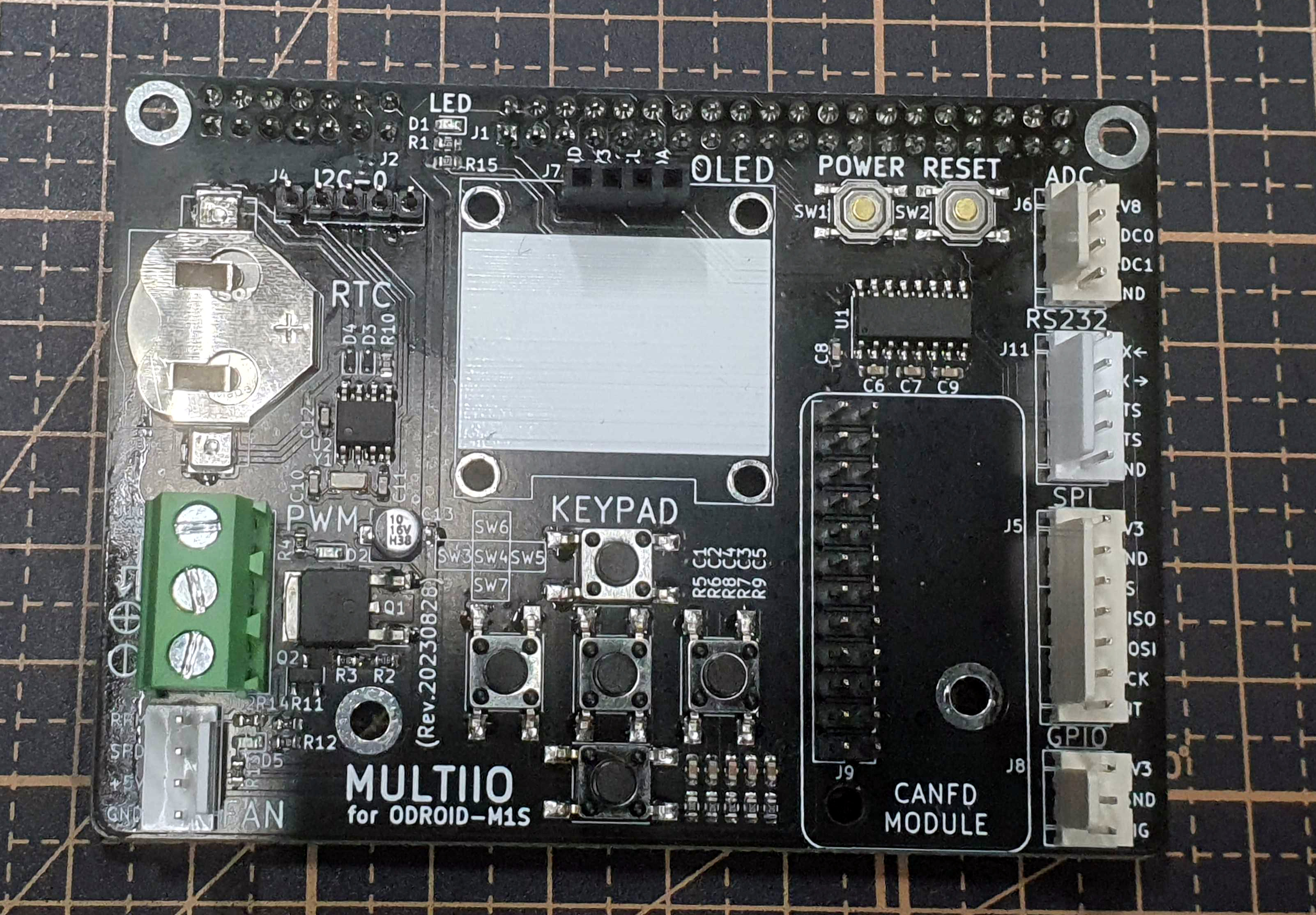
[Picture 1] MULTIIO
This board is designed to interface with the ODROID-M1S.
It was created to improve the process of selecting interfaces in /boot/config.ini and identifying pin locations.
It allows for simultaneous use of all interfaces, with each interface clearly labeled on the MULTIIO board.
Using MULTIIO
Below are the usage instructions and descriptions for MULTIIO.
Getting Started with MULTIIO
First, prepare the ODROID-M1S and MULTIIO boards.
Connect the MULTIIO board to the M1S while the power is off.
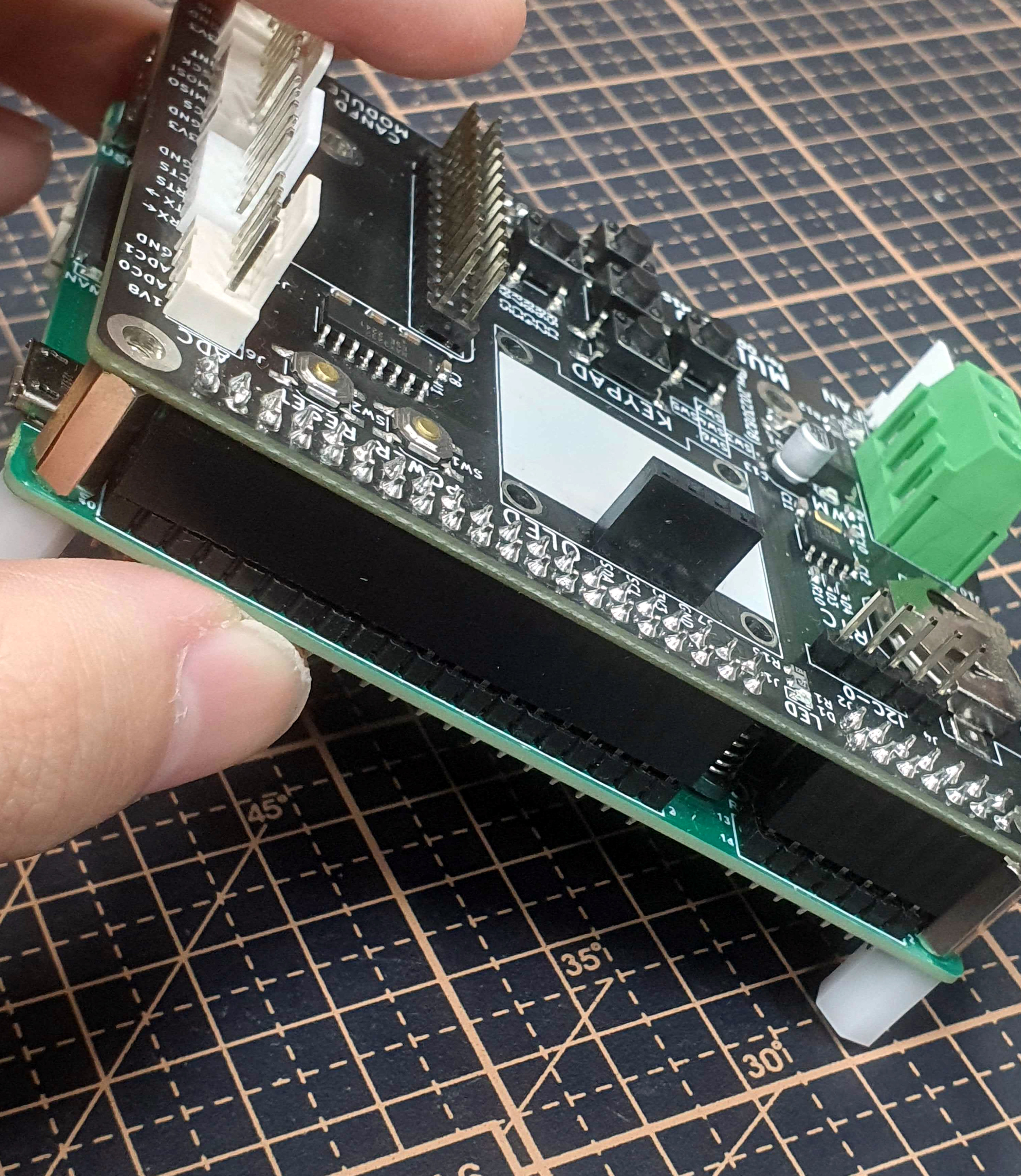
[Picture 2] m1s and multiio
Download the Ubuntu image for the M1S from the official site,
flash it to the M1S eMMC, and boot the system.
Modify /boot/config.ini on the M1S as follows:
[generic]
#default_console=ttyFIQ0
overlay_resize=16384
overlay_profile=
overlays="board_multiio"

[overlay_custom]
overlays="i2c0 i2c1"

[overlay_hktft32]
overlays="hktft32 ads7846"
reboot the system.
MULTIIO Interfaces
The MULTIIO board provides various interfaces including canfd, gpio, and i2c.
gpio
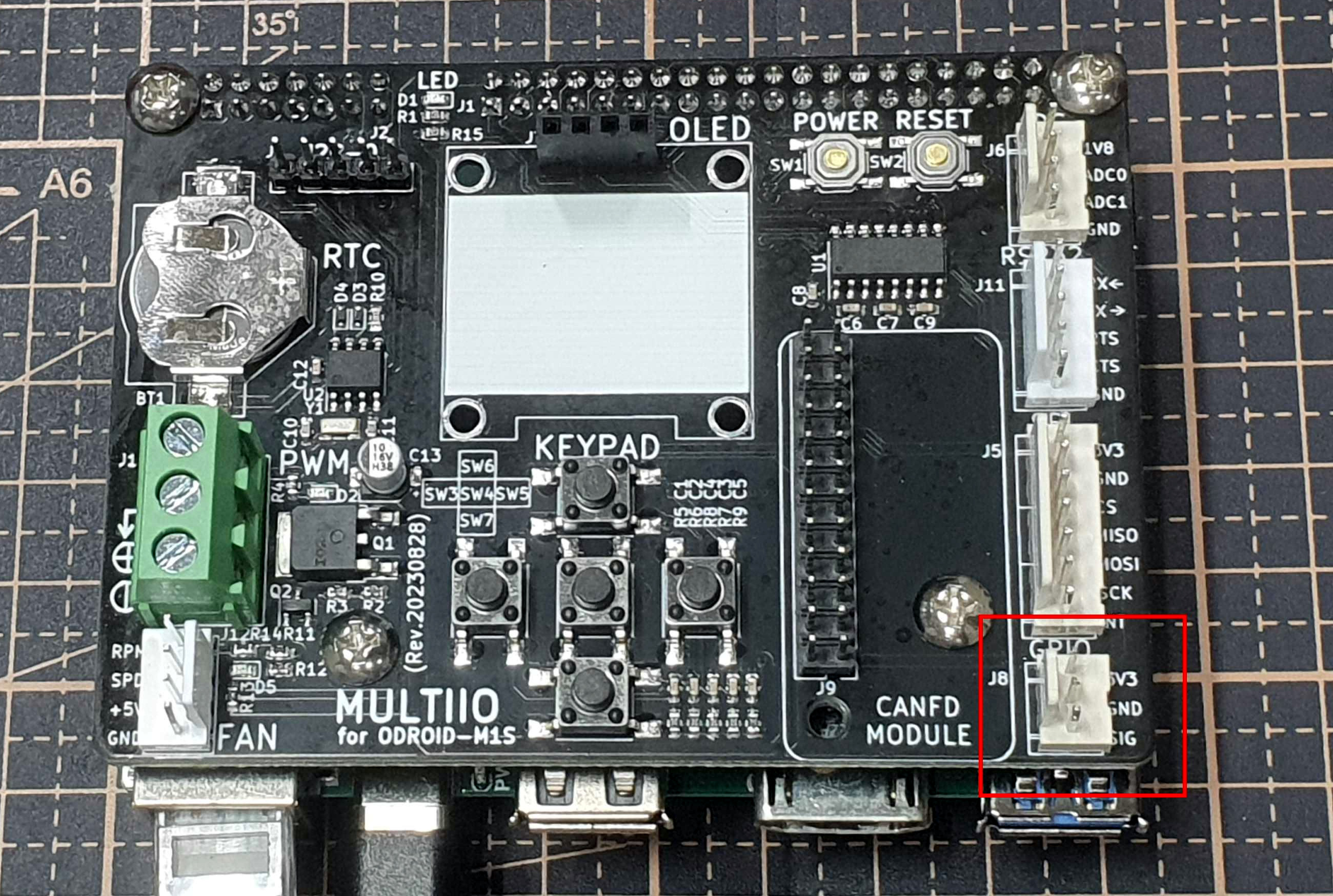
[Picture 3] multiio gpio
You can easily test sensors or devices controllable via GPIO.
The sysfs number is 14, and it can be controlled with root privileges.
$ echo 14 | sudo tee /sys/class/gpio/export
INPUT
$ echo in | sudo tee /sys/class/gpio/gpio14/direction
$ cat /sys/class/gpio/gpio14/value
OUTPUT
$ echo out | sudo tee /sys/class/gpio/gpio14/direction
$ echo [1|0] | sudo tee /sys/class/gpio/gpio14/value
i2c
I2C is straightforward, and additional examples are available on the Wiki.
I recommend referring to the Wiki.
input-device
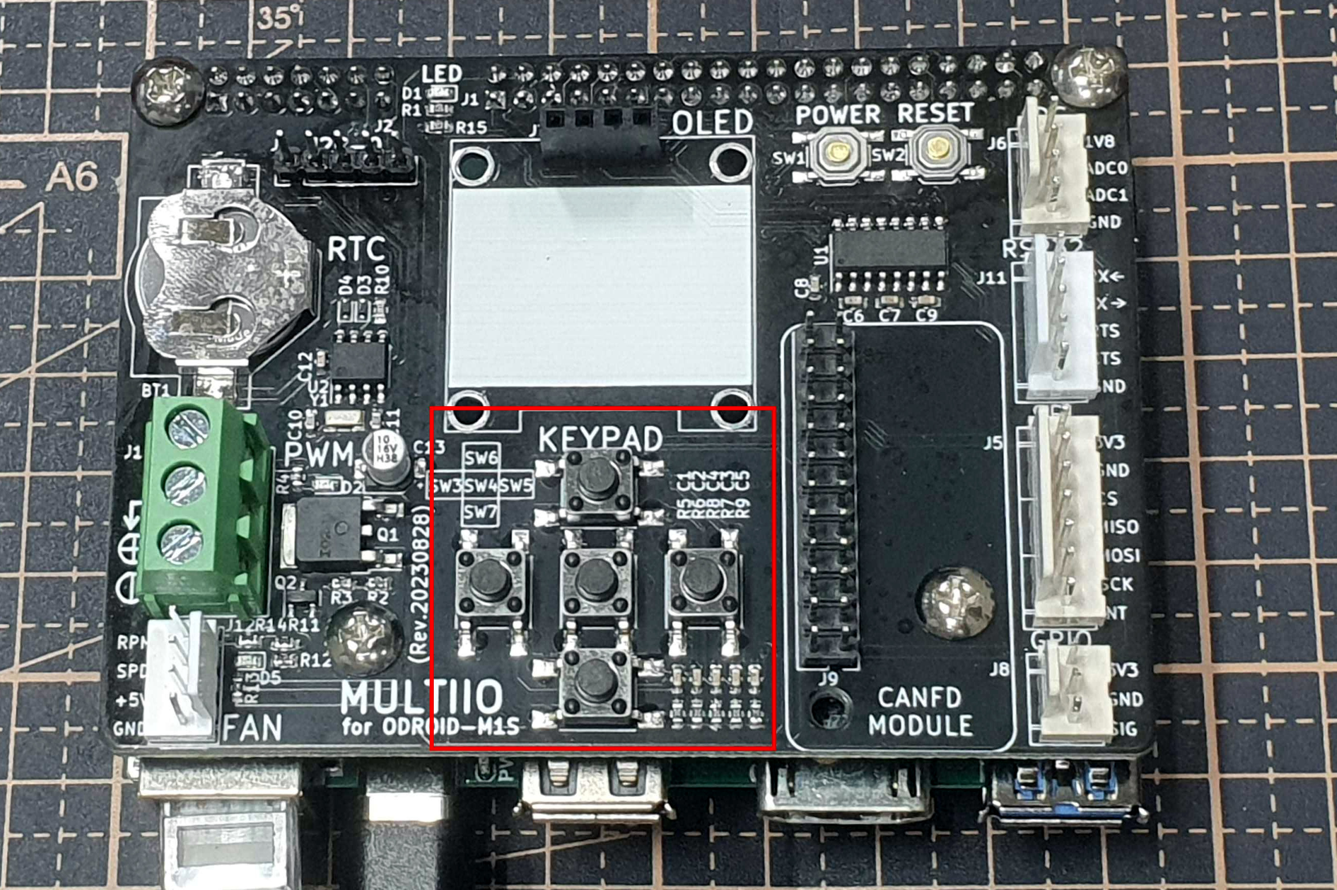
[Picture 4] multiio keypad
The MULTIIO board supports a keypad.
This keypad can be used to develop various applications.
Let’s test the keypad using evtest.
Install evtest.
$ sudo apt install evtest
Identify the keypad device.
$ ls -l /dev/input/by-path/platform-key_pad-event
lrwxrwxrwx 1 root root 9 Nov 10 01:09 /dev/input/by-path/platform-key_pad-event -> ../event2
Run evtest on event2.
$ sudo evtest --grab /dev/input/event2
Input driver version is 1.0.1
Input device ID: bus 0x19 vendor 0x1 product 0x1 version 0x100
Input device name: "key_pad"
Supported events:
  Event type 0 (EV_SYN)
  Event type 1 (EV_KEY)
    Event code 28 (KEY_ENTER)
    Event code 103 (KEY_UP)
    Event code 105 (KEY_LEFT)
    Event code 106 (KEY_RIGHT)
    Event code 108 (KEY_DOWN)
Key repeat handling:
  Repeat type 20 (EV_REP)
    Repeat code 0 (REP_DELAY)
      Value    250
    Repeat code 1 (REP_PERIOD)
      Value     33
Properties:
Testing ... (interrupt to exit)
Verify that events are printed whenever a key is pressed.
rtc
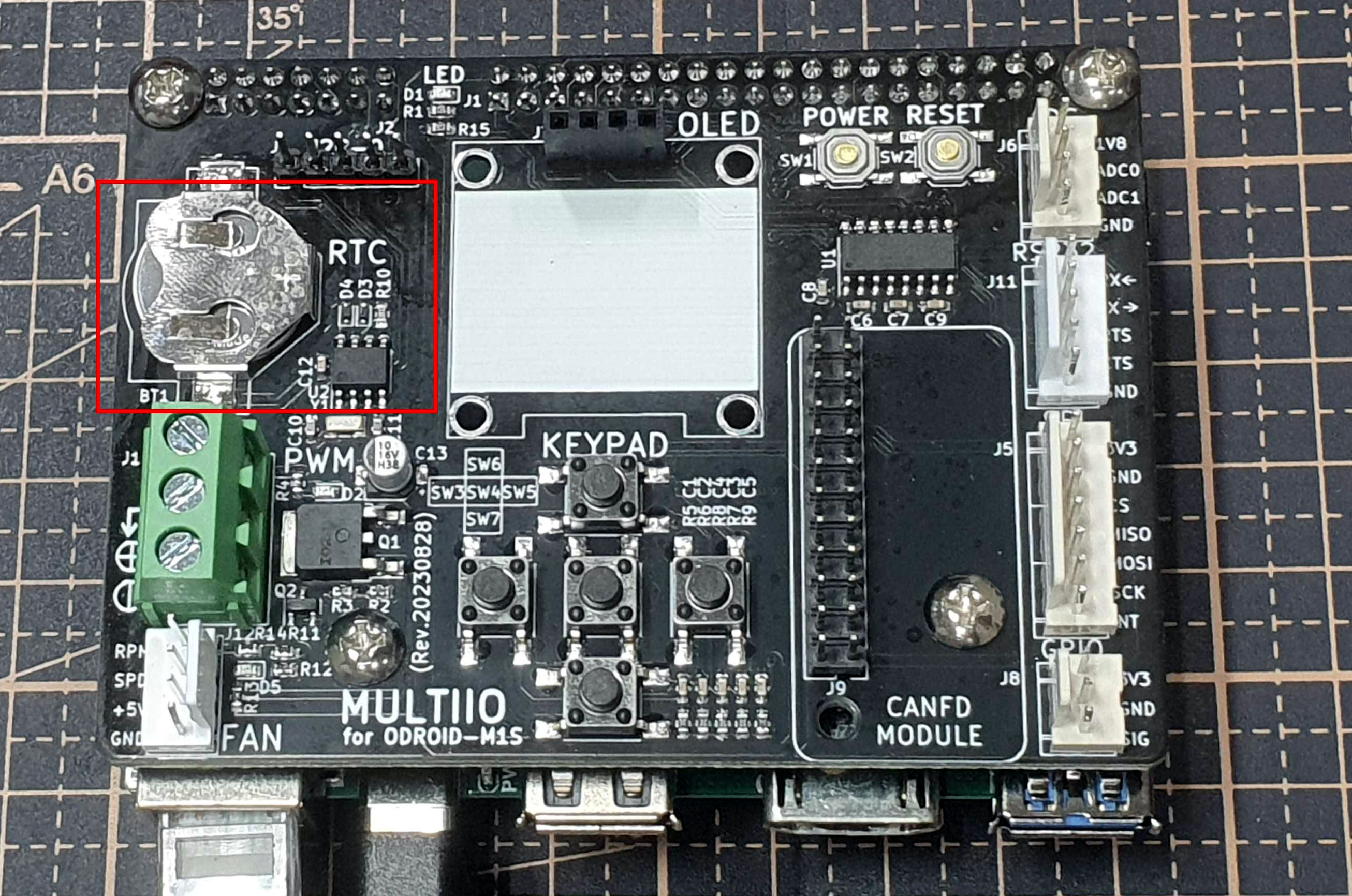
[Picture 5] multiio rtc
While the M1S has a built-in RTC, MULTIIO also supports one.
To use the MULTIIO RTC, you must switch from the default system RTC to the MULTIIO RTC.
The coin battery is sold separately.
Among various methods, I’ll use systemd to select and automatically initialize the RTC during boot.
First, create the udev rules.
$ echo "KERNEL==\"rtc1\", TAG+=\"systemd\"" | sudo tee /etc/udev/rules.d/50-rtc.rules
Define the service.
$ sudo vi /lib/systemd/system/hwrtc.service
[Unit]
Description=Synchronise System clock to hardware RTC
DefaultDependencies=no
Wants=dev-rtc1.device
After=dev-rtc1.device
Before=systemd-journald.service time-sync.target sysinit.target shutdown.target
Conflicts=shutdown.target

[Service]
Type=oneshot
RemainAfterExit=yes
ExecStart=/sbin/hwclock --hctosys --rtc=/dev/rtc1 -v --utc --noadjfile
RestrictRealtime=yes

[Install]
WantedBy=sysinit.target
In the Unit section, dev-rtc1.device refers to the device node /dev/rtc1.
Enable the service.
$ sudo systemctl enable hwrtc
$ sudo reboot
After rebooting, check the service status.
$ sudo service hwrtc status
_ hwrtc.service - Synchronise System clock to hardware RTC
     Loaded: loaded (/lib/systemd/system/hwrtc.service; enabled; vendor preset: enabled)
     Active: active (exited) since Fri 2023-11-10 01:39:26 UTC; 2min 4s ago
    Process: 316 ExecStart=/sbin/hwclock --hctosys --rtc=/dev/rtc1 -v --utc --noadjfile (code=exited, st>
   Main PID: 316 (code=exited, status=0/SUCCESS)

Nov 10 01:39:26 server hwclock[316]: Using the rtc interface to the clock.
Nov 10 01:39:26 server hwclock[316]: Assuming hardware clock is kept in UTC time.
Nov 10 01:39:26 server hwclock[316]: Waiting for clock tick...
Nov 10 01:39:26 server hwclock[316]: ...got clock tick
Nov 10 01:39:26 server hwclock[316]: Time read from Hardware Clock: 2023/11/10 01:39:26
Nov 10 01:39:26 server hwclock[316]: Hw clock time : 2023/11/10 01:39:26 = 1699580366 seconds since 1969
Nov 10 01:39:26 server hwclock[316]: Time since last adjustment is 1699580366 seconds
Nov 10 01:39:26 server hwclock[316]: Calculated Hardware Clock drift is 0.000000 seconds
Nov 10 01:39:26 server hwclock[316]: Calling settimeofday(NULL, 0) to lock the warp_clock function.
Nov 10 01:39:26 server hwclock[316]: Calling settimeofday(1699580366.000000, NULL) to set the System tim>
lines 1-16/16 (END)...skipping...
You can use the following commands for the RTC:
$ sudo hwclock -[r|s|w]
spi
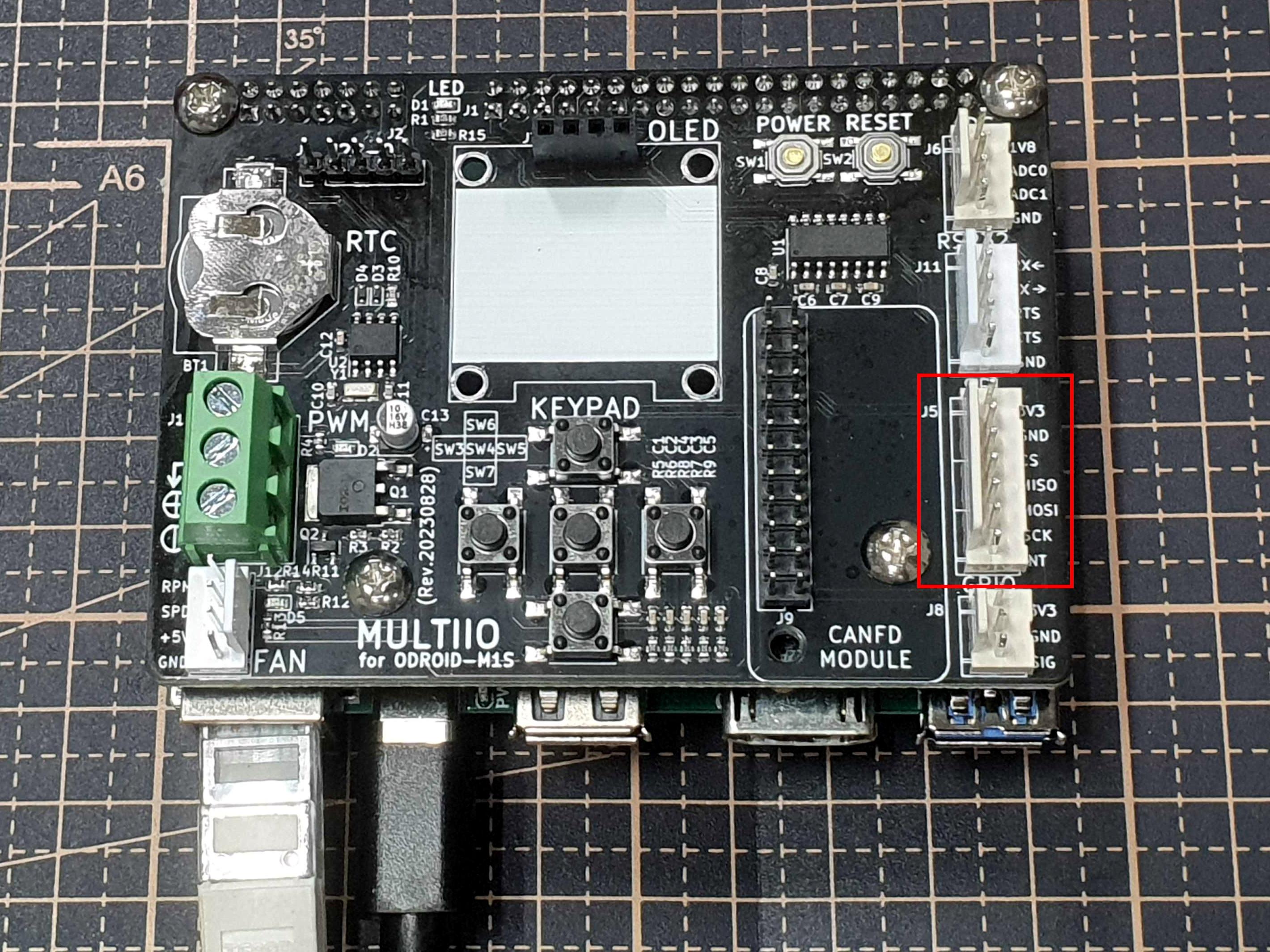
[Picture 6] multiio spi
The MULTIIO board also provides an SPI interface.
It provides spidev by default, which can be replaced with a specific SPI device driver in the DTB.
$ ls /dev/spidev0.0
/dev/spidev0.0
pwm
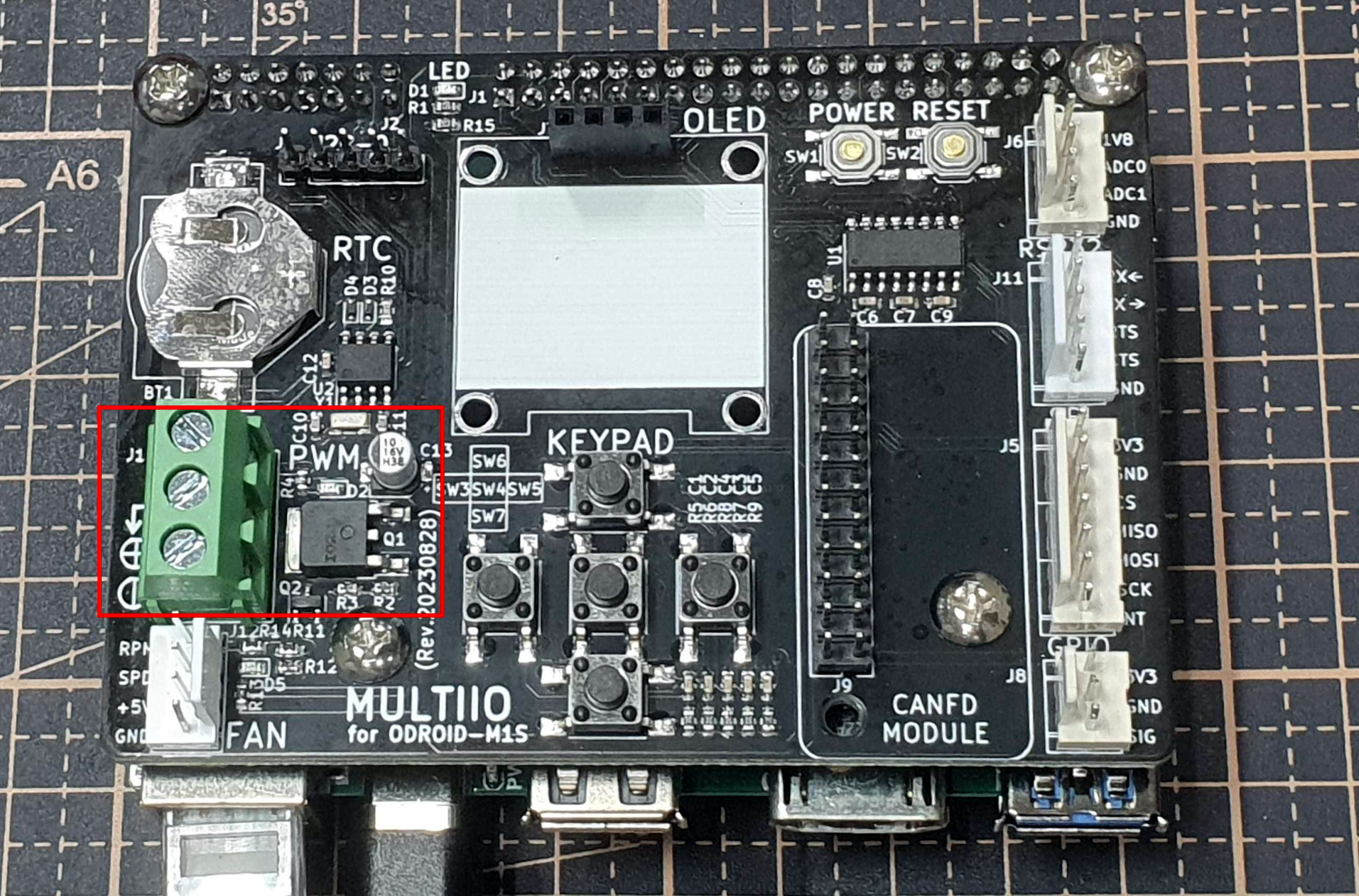
[Picture 7-1] multiio pwm
It supports the PWM interface. PWM requires an external power supply.
Note: Depending on their specifications, peripherals using PWM may damage the board.
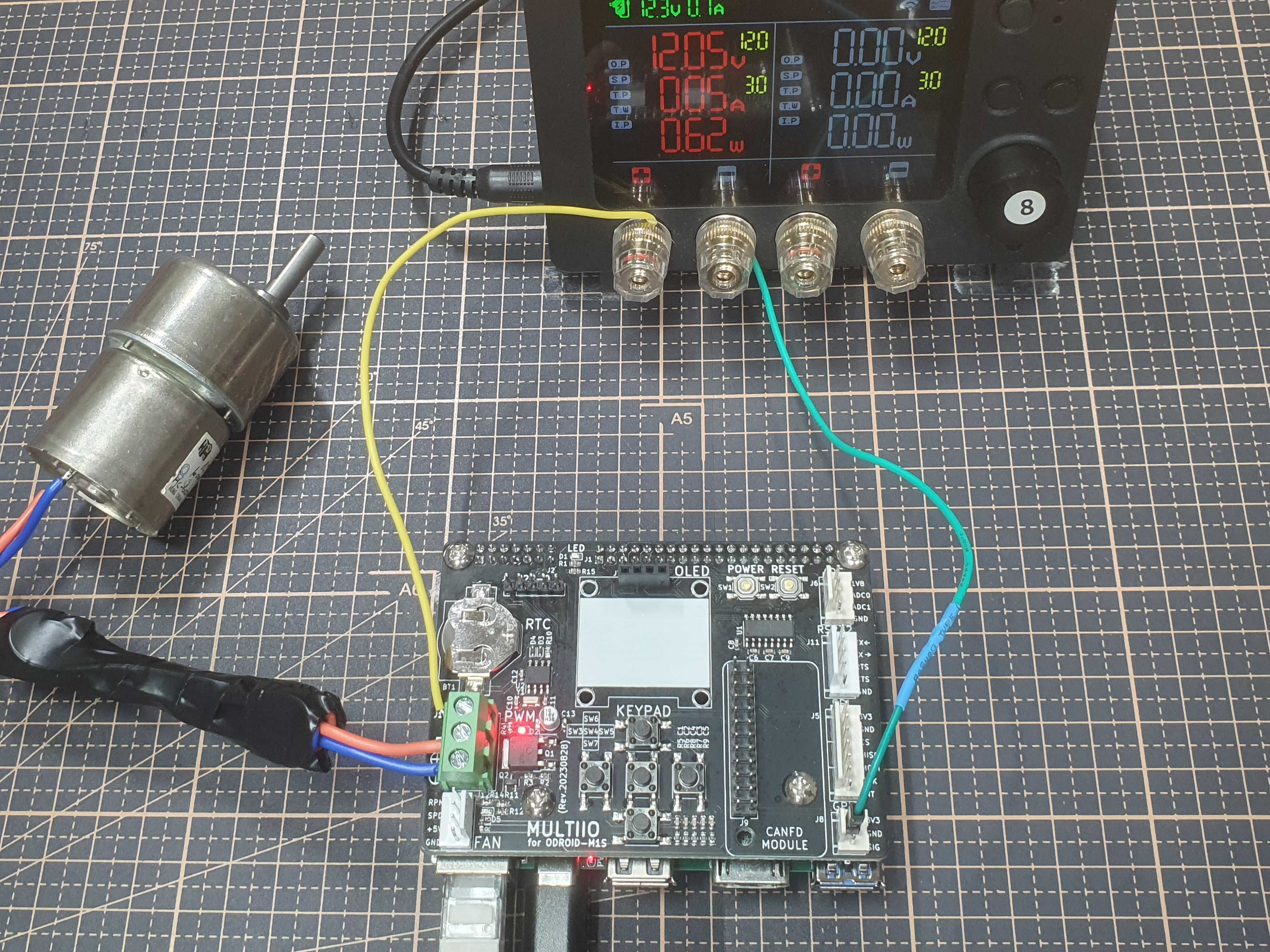
[Picture 7-2] multiio pwm example
Although I used a motor with Smart Power3 as a PWM example,
this photo is a simple example of supplying external power to the motor.
Exercise caution when using Smart Power3 as a power source.
When using high-output motors, you must use a separate motor driver that matches the specifications.
Smart Power3 is also not suitable as an external power source in such cases.
For high-spec motors, please use an external power source such as a high-output SMPS, lithium battery, or professional power supply.
rs232
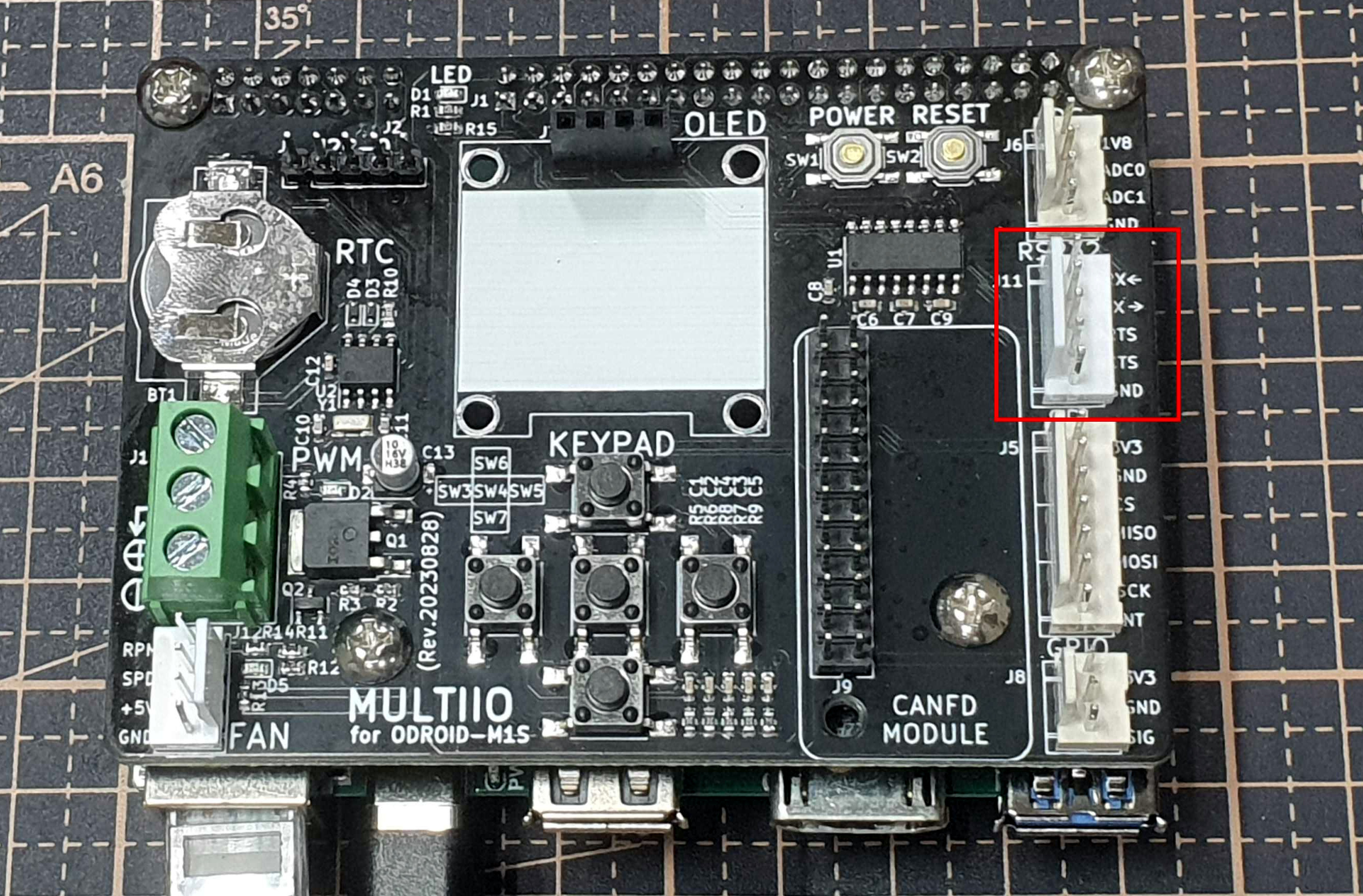
[Picture 8] multiio rs232
It can be connected to a computer using a USB-to-Serial Cable.
hardware flow control is also supported.
You can test hardware flow control by connecting and disconnecting the cts-rts lines.
Check the device node.
$ ls /dev/ttyS?
/dev/ttyS0
Commands for RS232 operation:
$ sudo stty -F /dev/ttyS0 9600 -cstopb -parenb

# receive
$ cat /dev/ttyS0

# transmit
$ echo "123" | sudo tee /dev/ttyS0
canfd
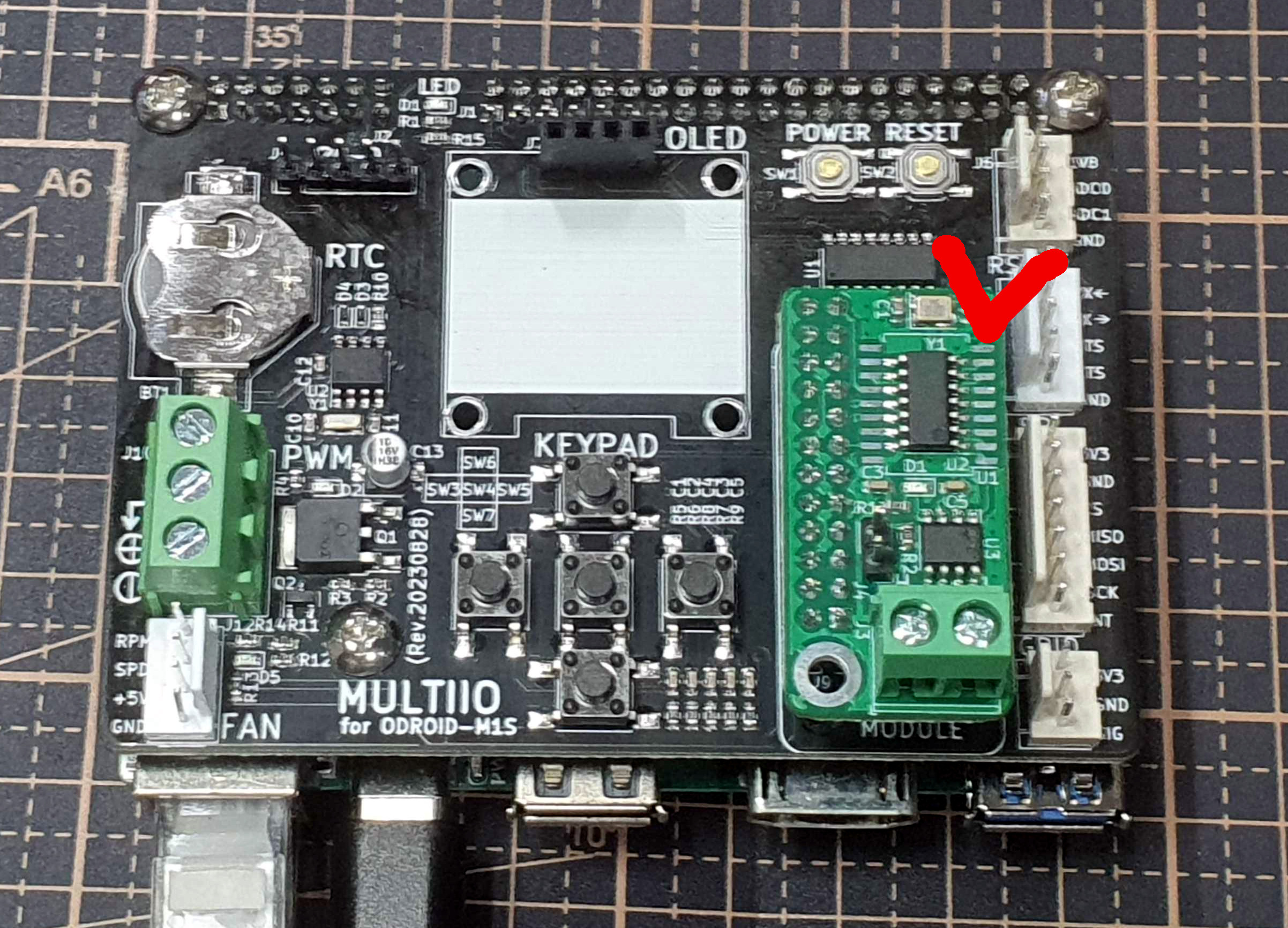
[Picture 9] multiio canfd
As you can see, an additional canfd module is required.
To use CAN-FD with MULTIIO, modify /boot/config.ini as follows:
[generic]
#default_console=ttyFIQ0
overlay_resize=16384
overlay_profile=
overlays="board_multiio board_multiio_canfd"

[overlay_custom]
overlays="i2c0 i2c1"

[overlay_hktft32]
overlays="hktft32 ads7846"
Check the CAN device.
$ lsmod
mcp251xfd              32768  0
can_dev                24576  1 mcp251xfd
Keen observers might notice that the M1S has native CAN-FD.
MULTIIO uses a CAN-FD module with an on-board mcp2517 chip.
The first reason is that certain issues occurred during the development phase.
Secondly, I wanted to ensure compatibility with CAN-FD modules.
Thirdly, the pin layout offers the advantage of supporting up to two CAN channels.
However, once issues are resolved or if the dual-channel advantage is deemed unnecessary, the CAN-FD module might be replaced with native CAN in future releases to enhance price competitiveness through cost reduction.
oled
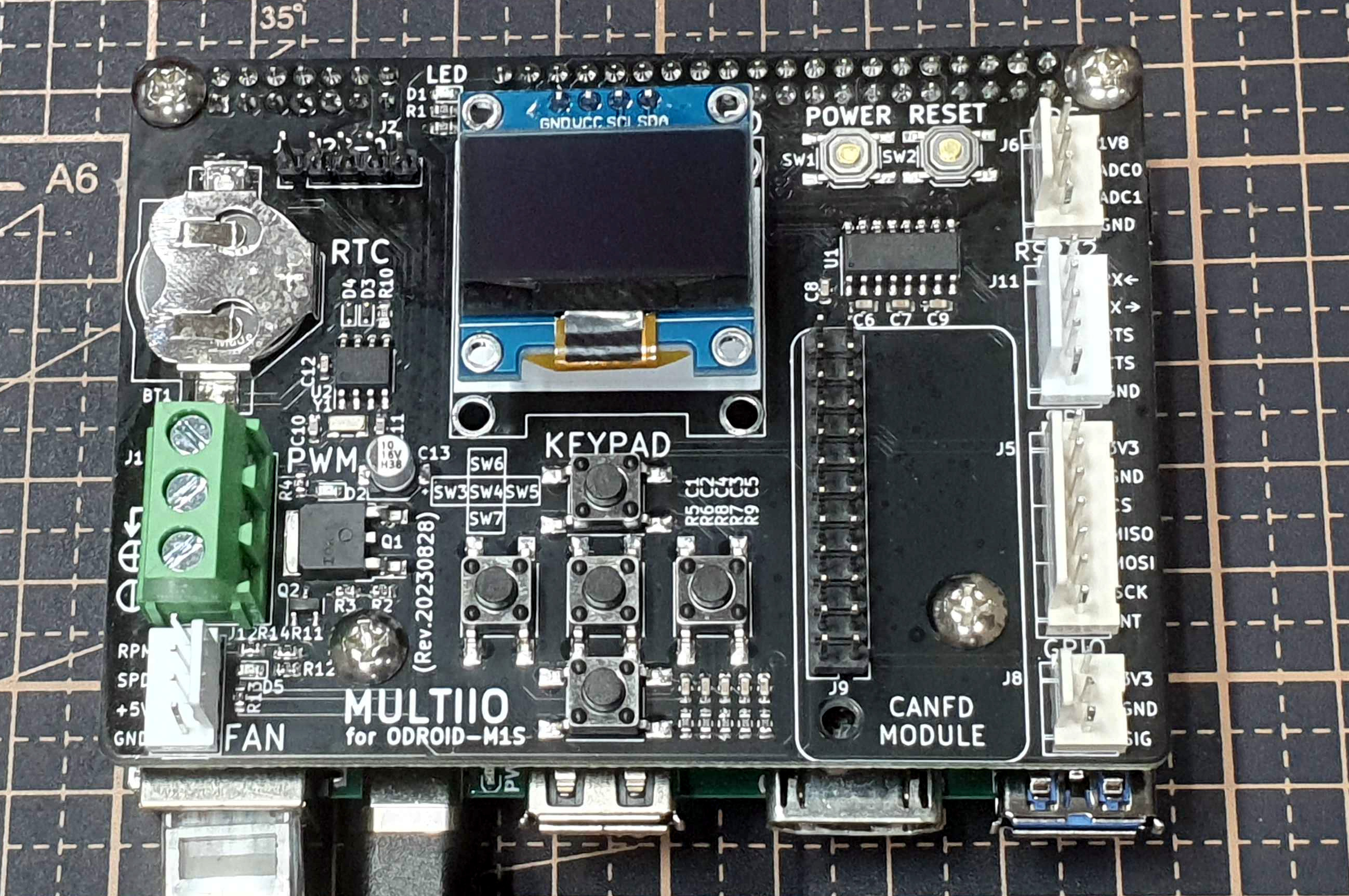
[Picture 10-1] multiio oled
To use the OLED module with MULTIIO, modify /boot/config.ini as follows:
[generic]
#default_console=ttyFIQ0
overlay_resize=16384
overlay_profile=
overlays="board_multiio board_multiio_oled"

[overlay_custom]
overlays="i2c0 i2c1"

[overlay_hktft32]
overlays="hktft32 ads7846"
Reboot.
$ sudo reboot
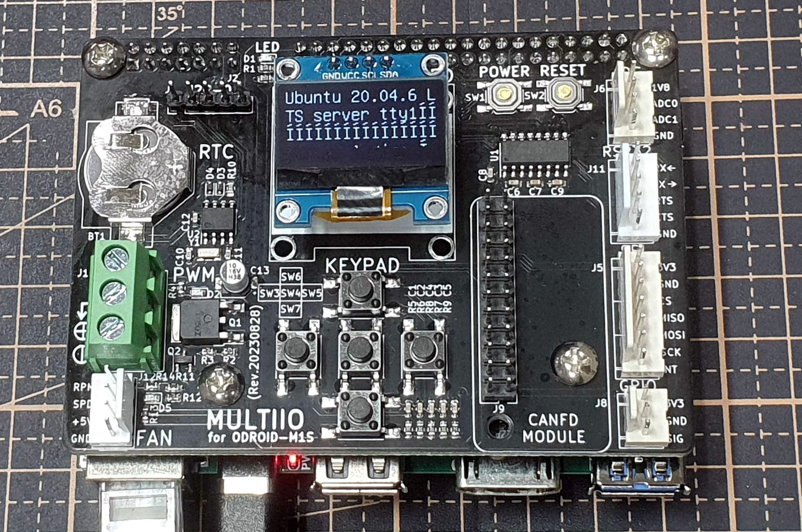
[Picture 10-2] multiio oled on
This is how it looks immediately after booting.
History (Pre-release Development Phase)
Although MULTIIO seems simple, debugging and testing it was not easy.
There were several releases prior to the final version.
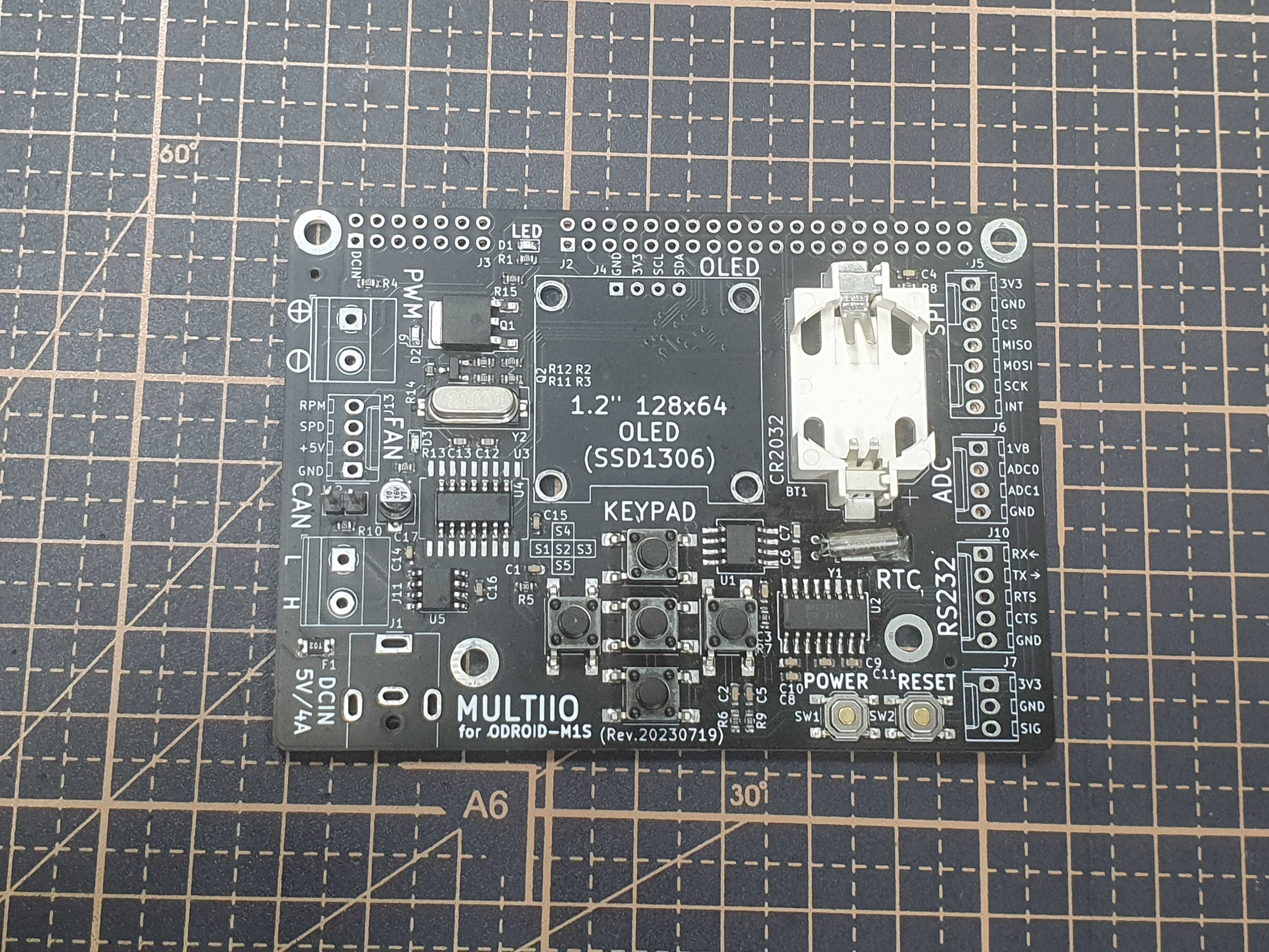
[Picture 11-1] multiio 20230719
It looks quite different from the current 20230810 version.
The differences are obvious when compared side-by-side.
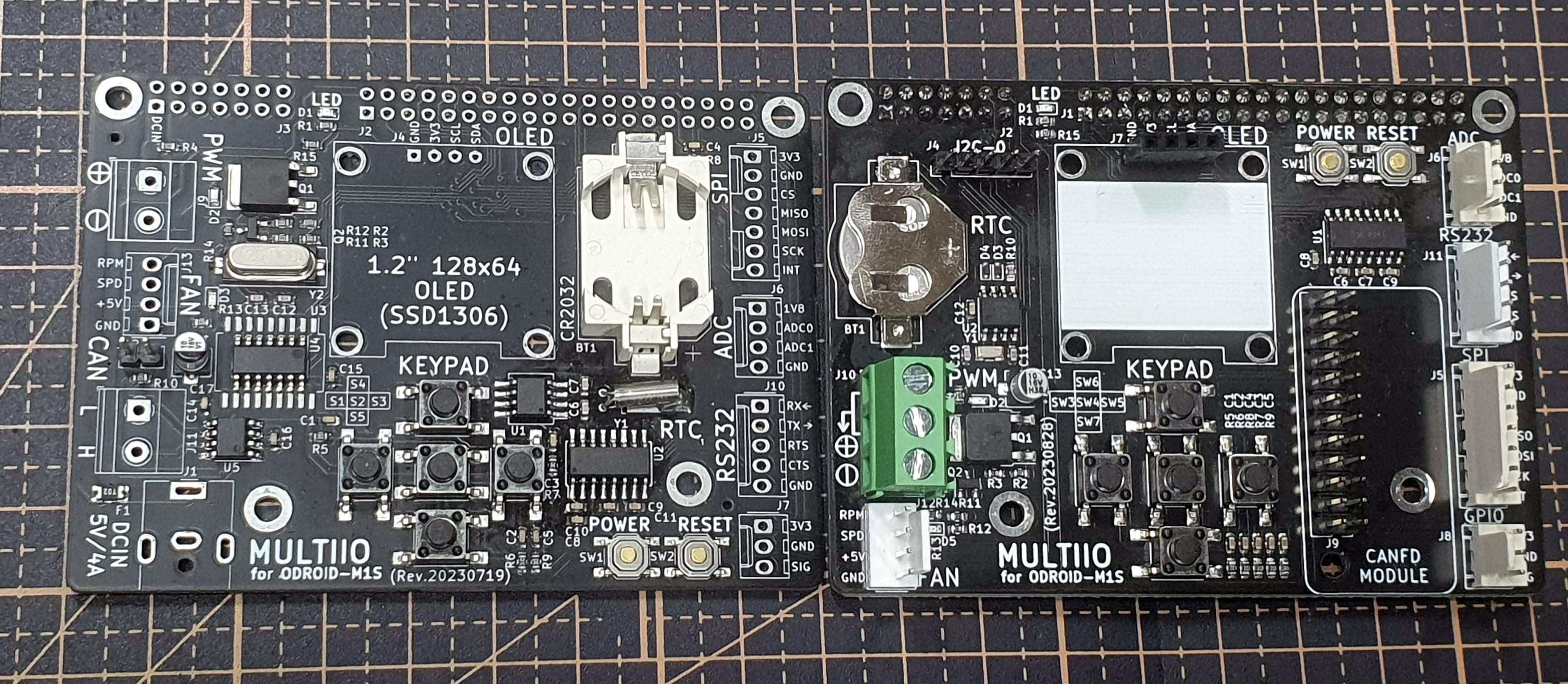
[Picture 11-2] 0719 vs 0810
The RTC coin battery became smaller, and CAN-FD was changed to an option using the mcp2517.
A lot of attention was paid to details during debugging.
Below are photos taken while debugging the older versions.
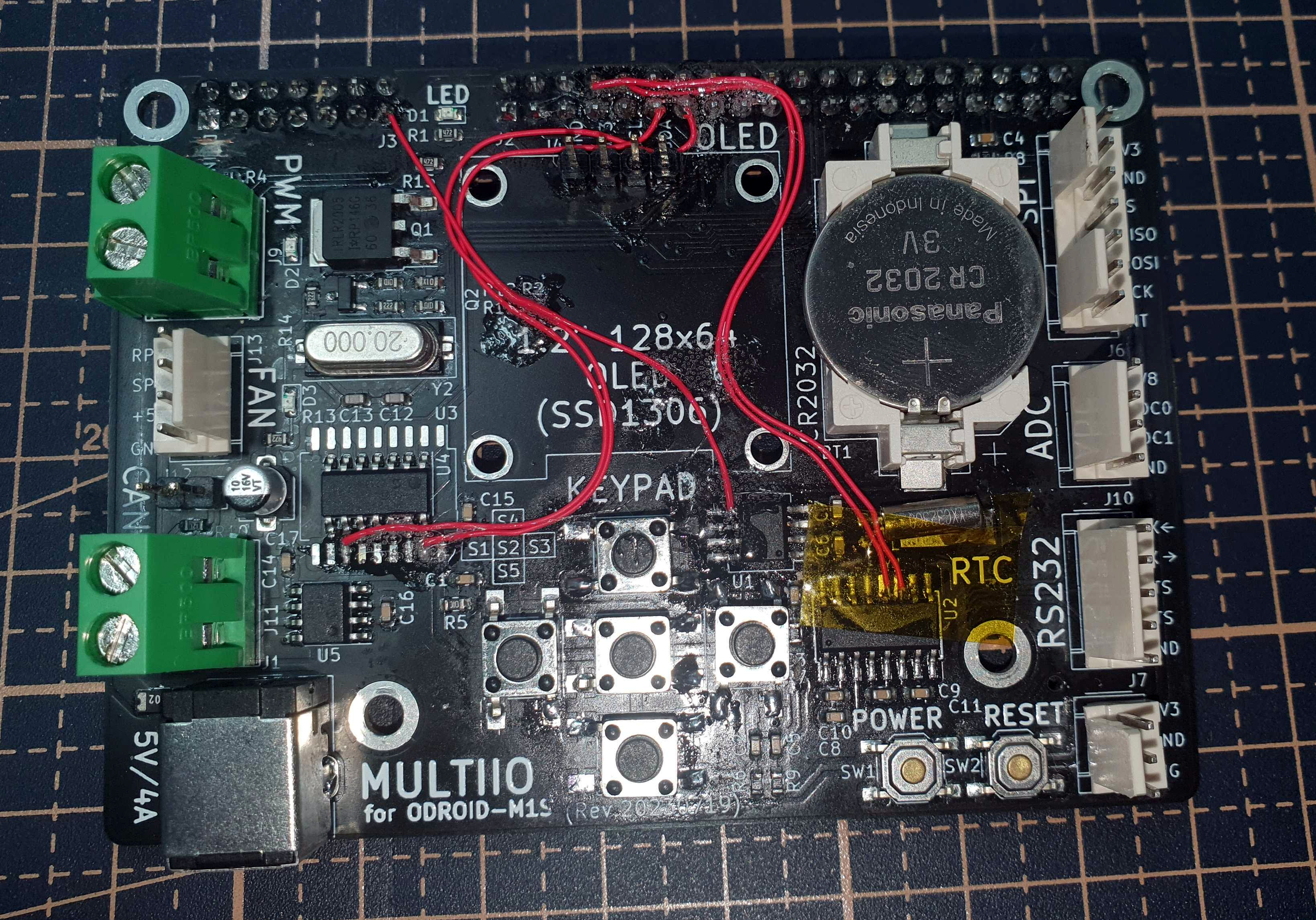
[Picture 12-1] multiio_debug 1
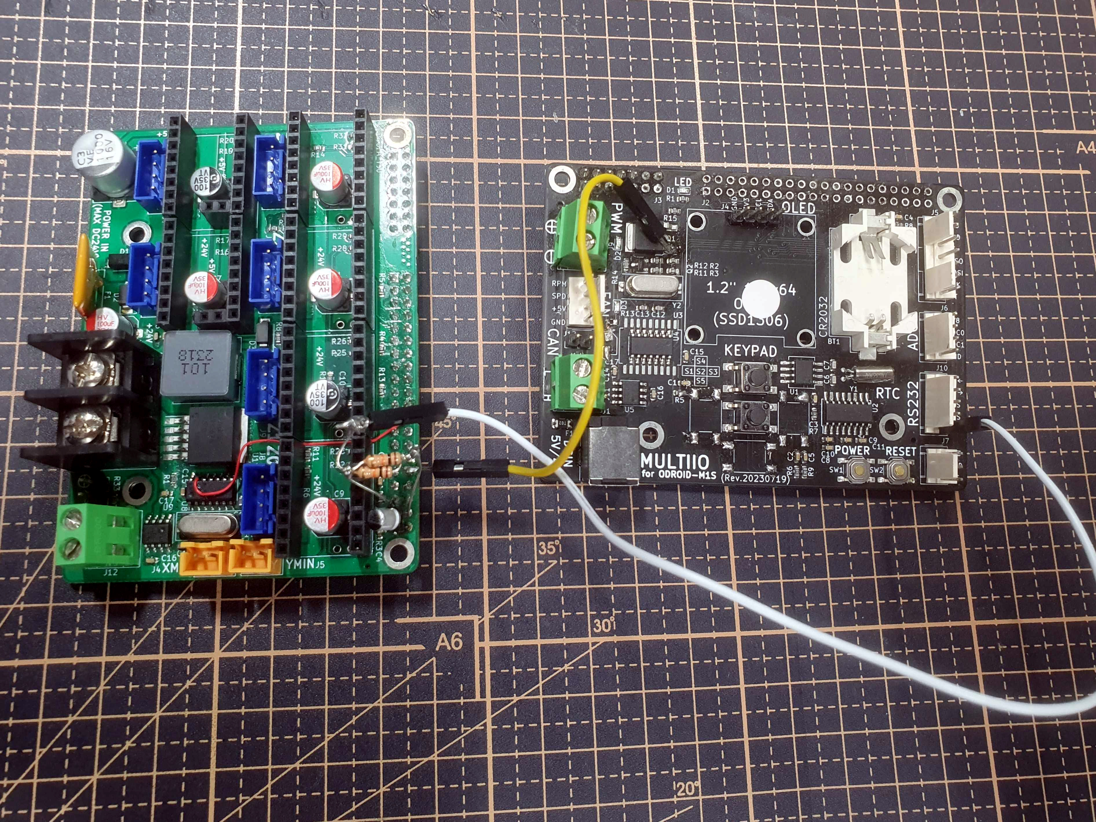
[Picture 12-2] multiio_debug 2
The second photo was taken while using parts of the MULTIIO circuit to test features of the M1S stepper board, which I’ll post about later.
Initially, I ambitiously set out to support all interfaces at once.
I thought the idea was great, unique to the market, and I still believe in it, but…
The debugging process and pre-launch testing were quite overwhelming; it was a challenging journey.
Still, seeing it released makes me very proud!
Finally, I hope many of you enjoy using it.
Purchase is available here.

Leave a comment