
[ODROID] 6-Axis Robot Construction Guide with ROS2 - Part 1
I’ve brought an interesting topic today.
I was thinking about making something fun with an Odroid and decided to pick up a robot arm I had at home.
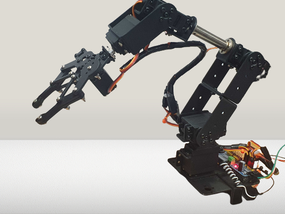
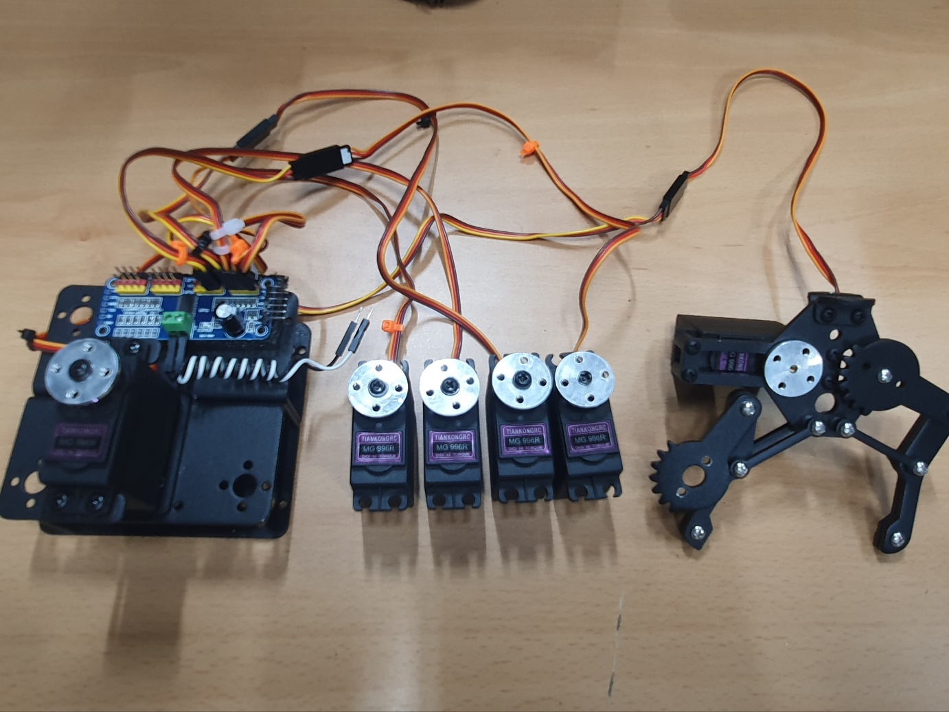
[picture 1] Six-Axis robot arm
You can purchase it at link or from local retailers.
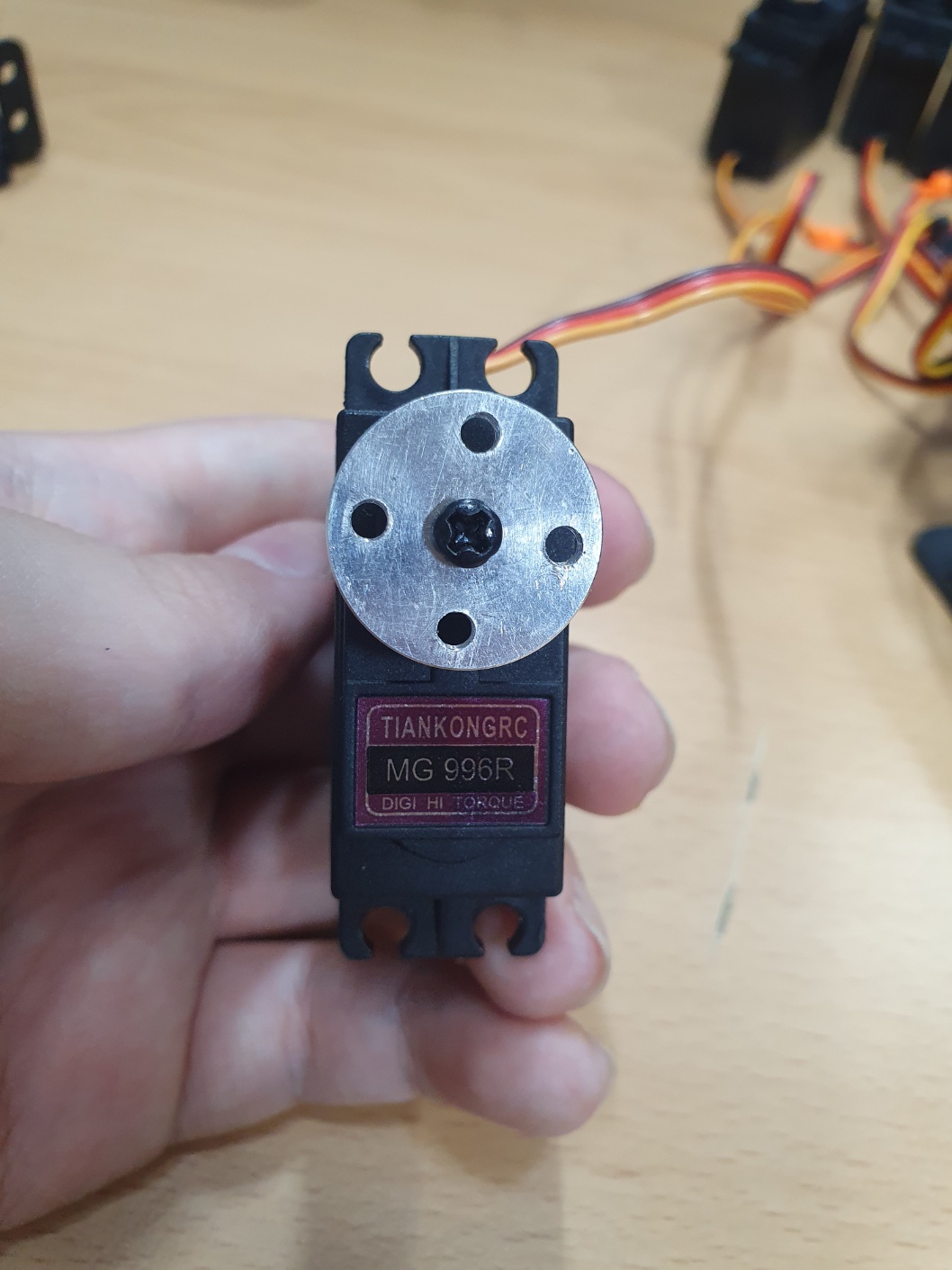
The motor driver ( pca9685 ) and motors (6x MG996R ) must be purchased separately.
While control can be implemented in C or Python, I chose ROS2 as I wanted to gain experience with it.
I’ll take my time to add features one by one and complete the project.
The requirements are as follows:
- Odroid C4       ... (x1)
- MG996R          ... (x6)
- PCA9685         ... (x1)
- Robot frame set ... (x1)
You need to set up the environment to use the pca9685 on the C4 board in advance.
Refer to this post and the package documentation for the setup.
For the OS, use the C4 ROS2 image.
Assembly
Surprisingly, there is no assembly manual for this product…
I wasn’t going to write about it, but since I had to assemble and disassemble it repeatedly, I’ve documented the process.
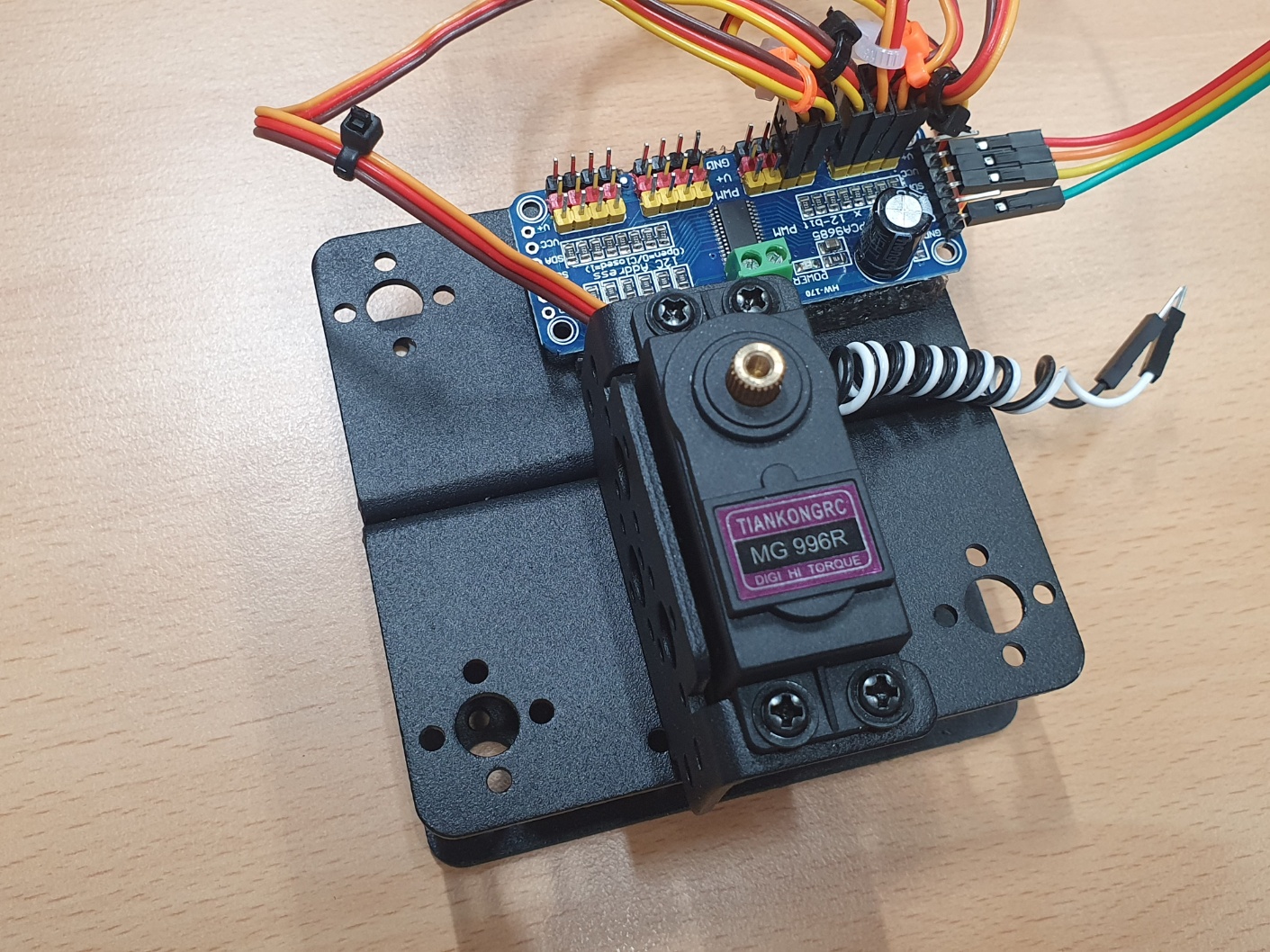
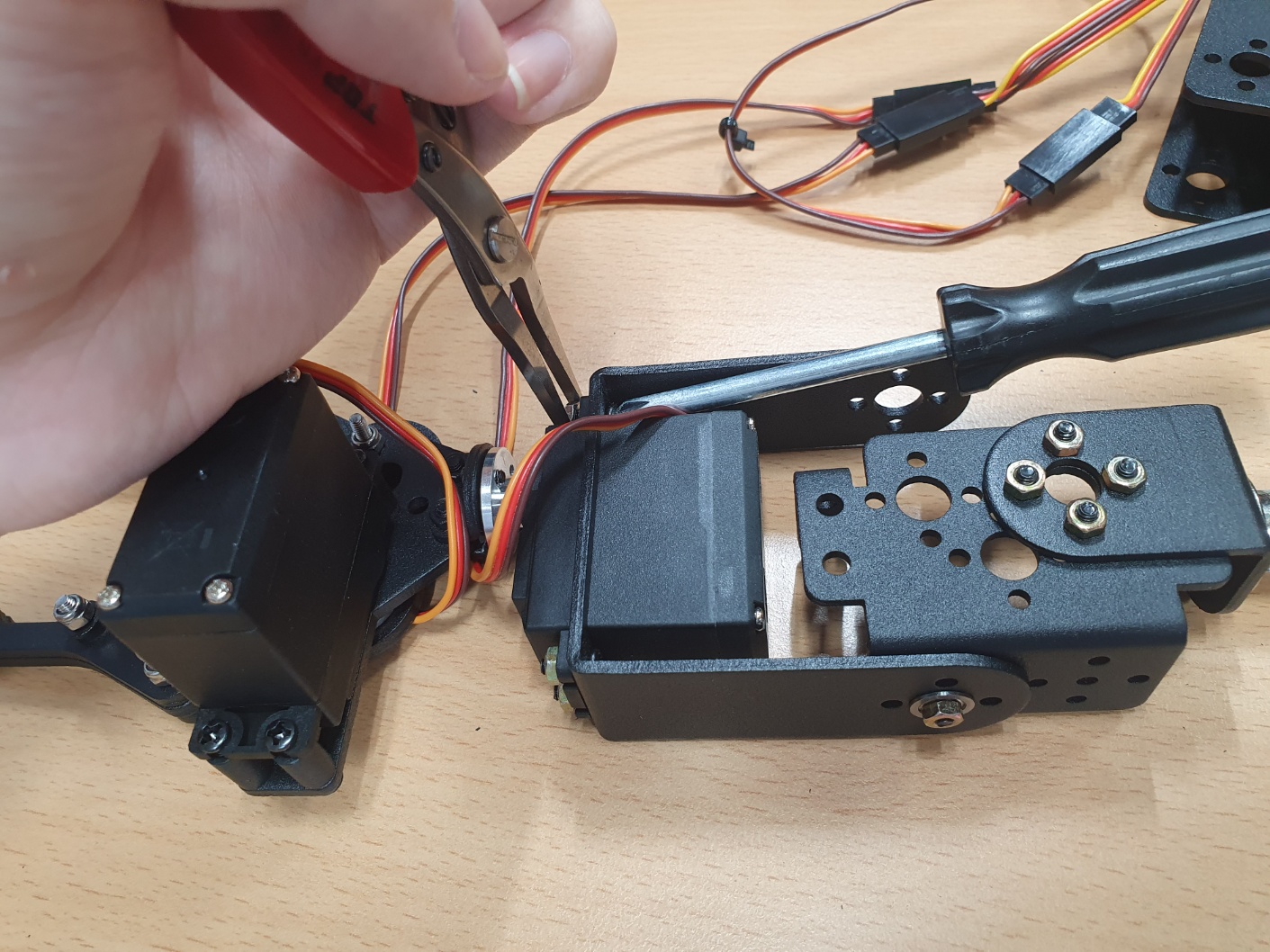
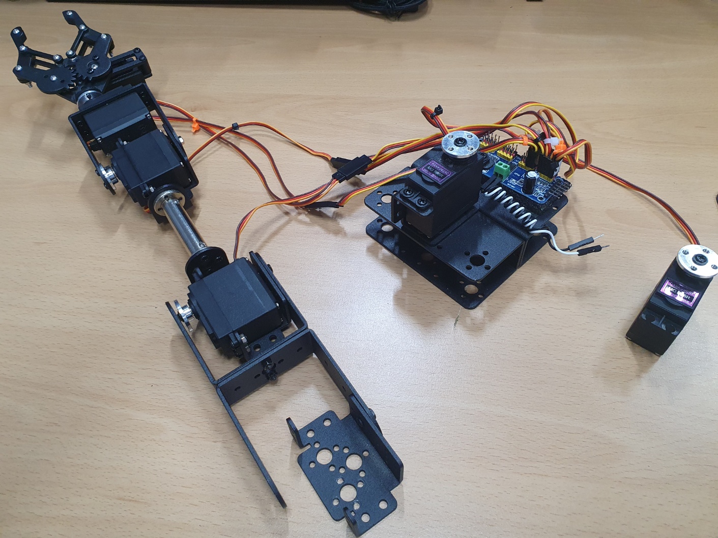
Assemble the parts as shown in the photos below.
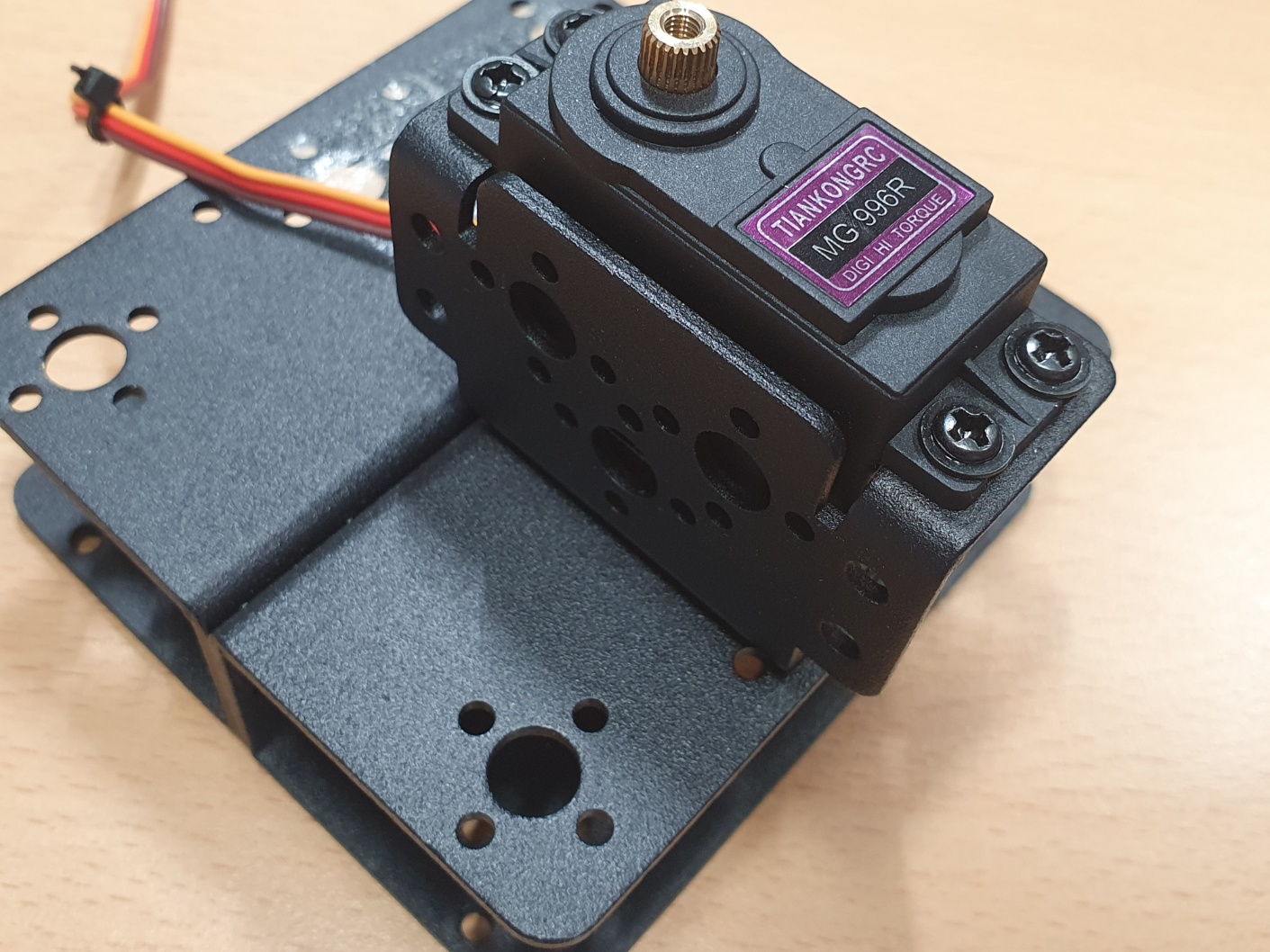
[picture 2] assembly 1
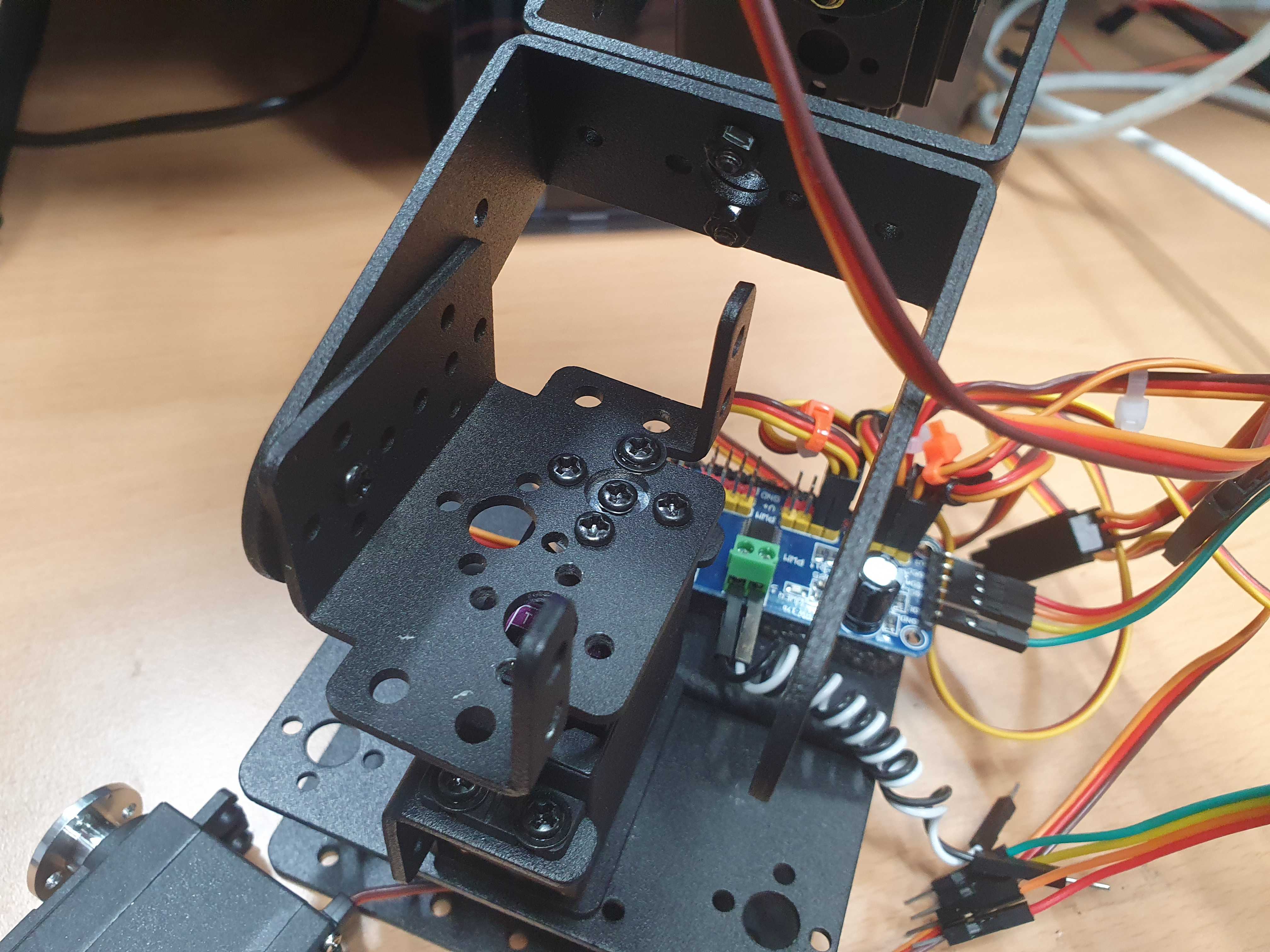
Connect the six MG996R motors to the pca9685 board.
After connecting them, attach them to the frame.
I cut and attached pieces of sponge from the frame’s packaging box.
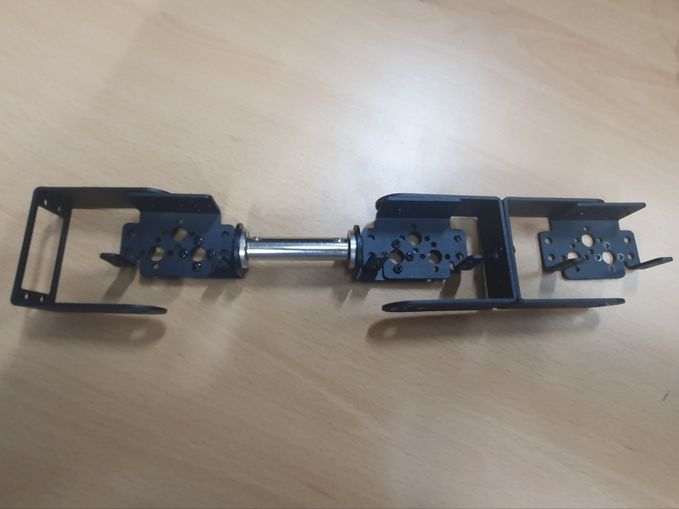
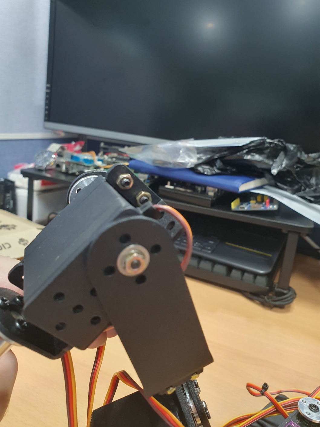
[picture 3] assembly 2
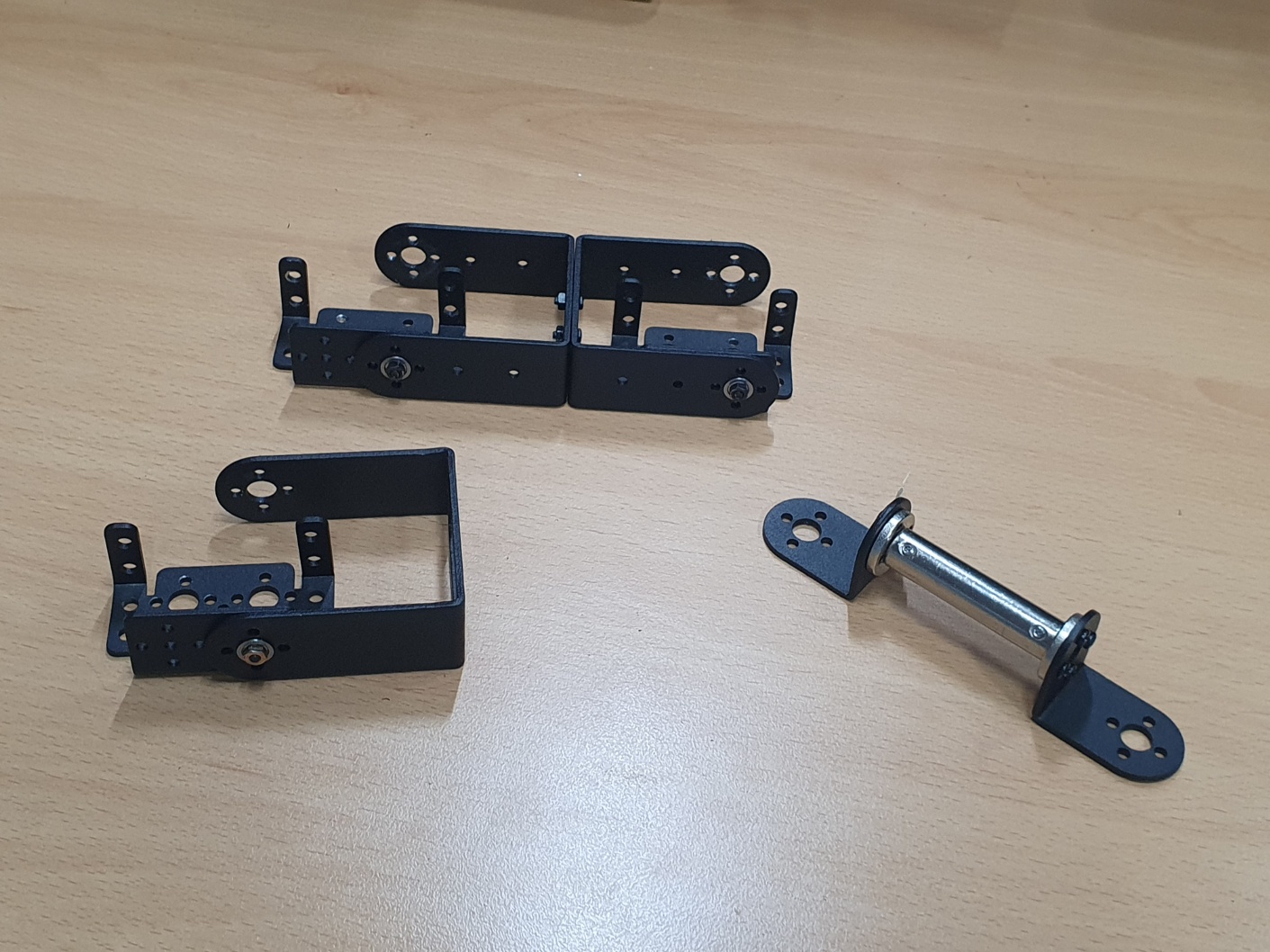
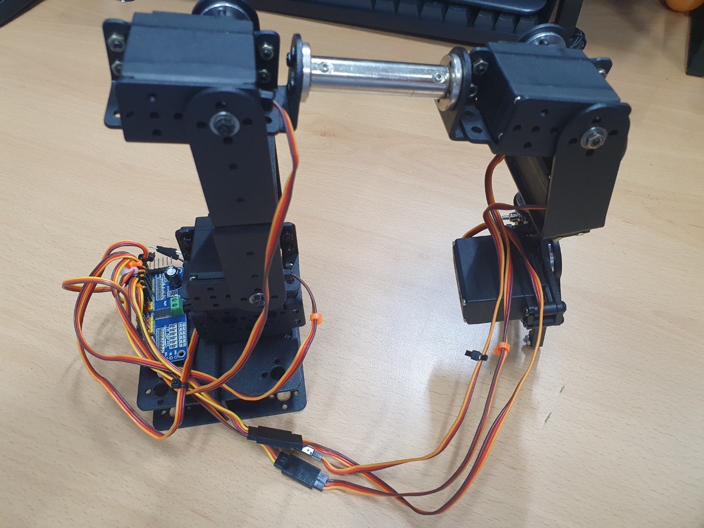
Combine the previously assembled parts to complete the arm.
[picture 4] assembly 3
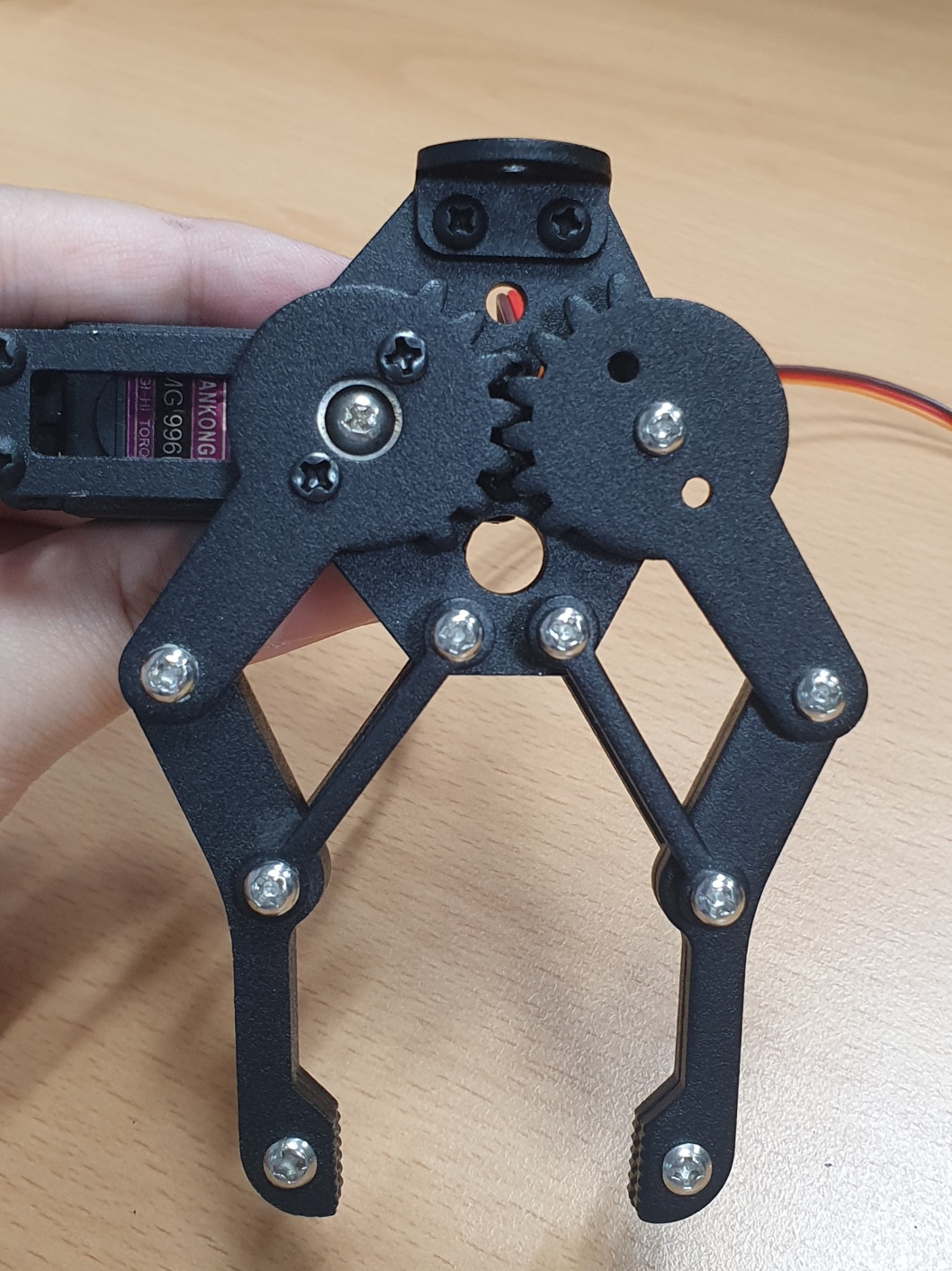
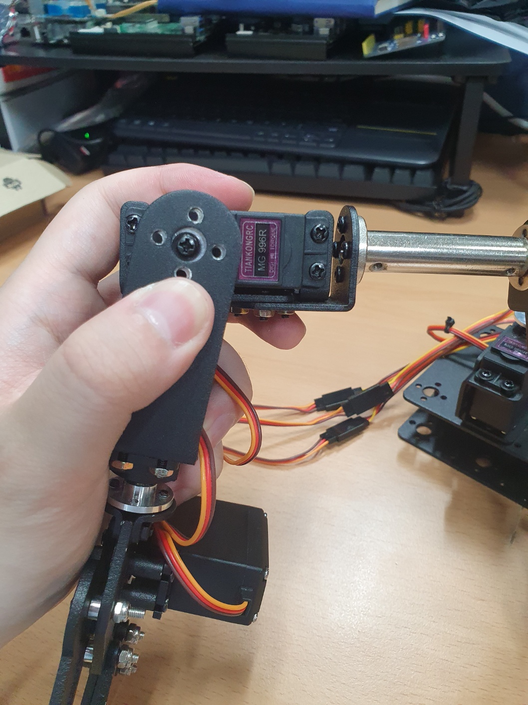
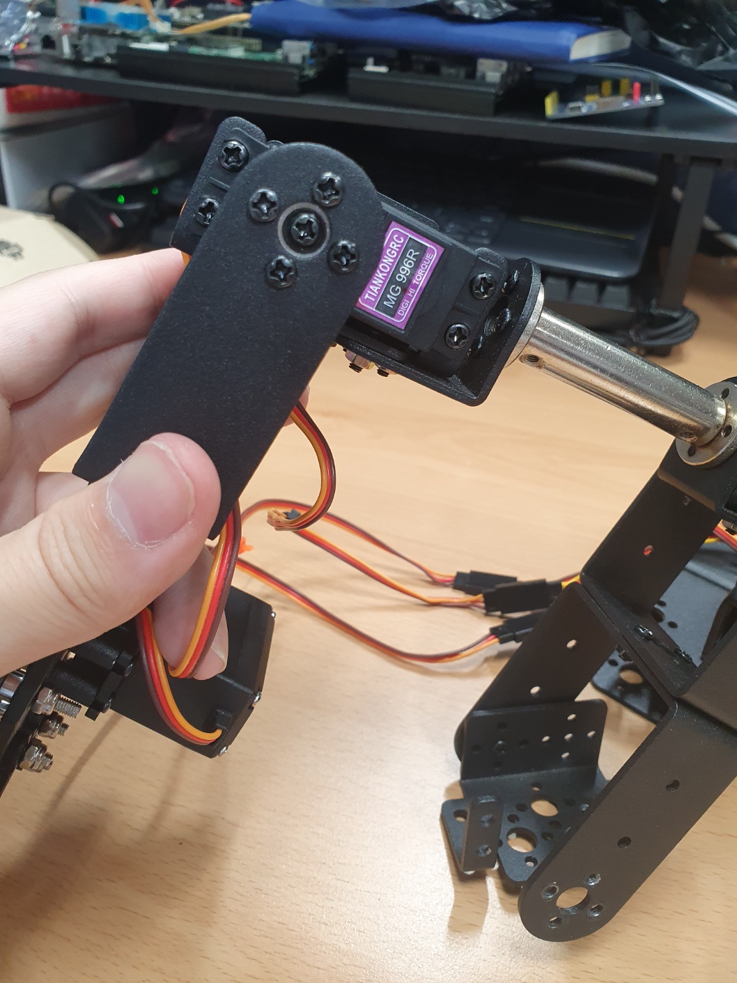
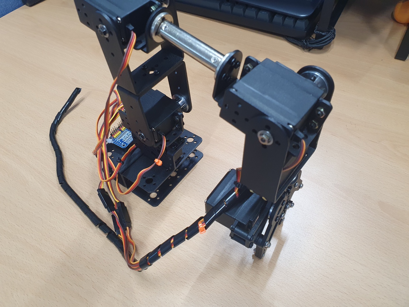
Assemble the gripper section.
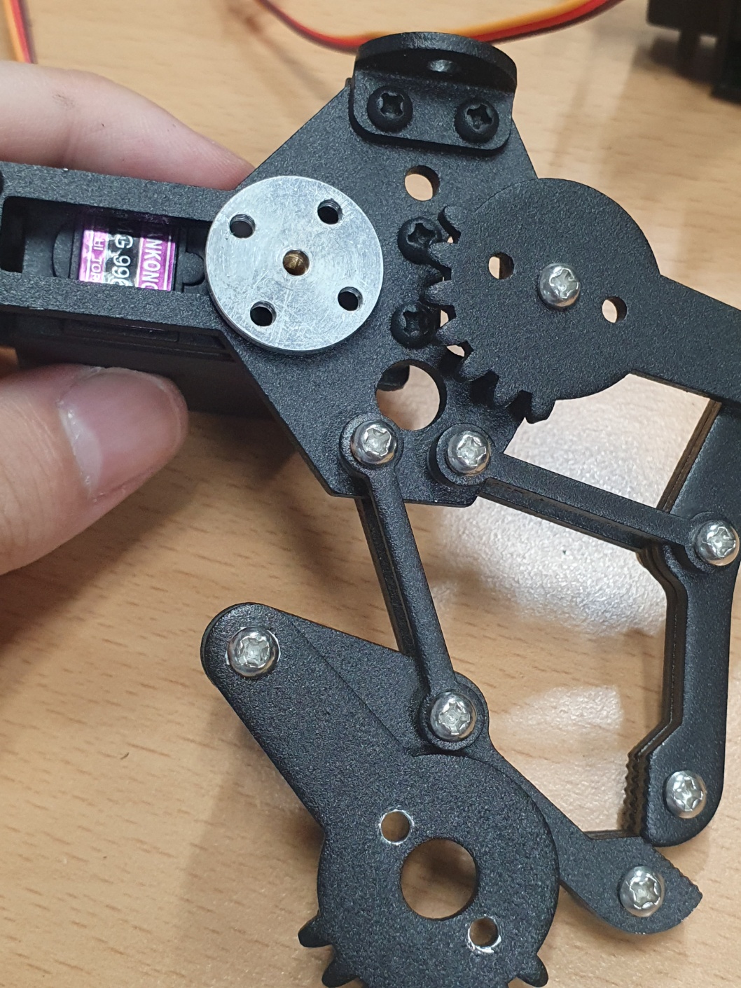
[picture 4] assembly 3
If you’ve followed along so far, the assembly should look like the following photo.
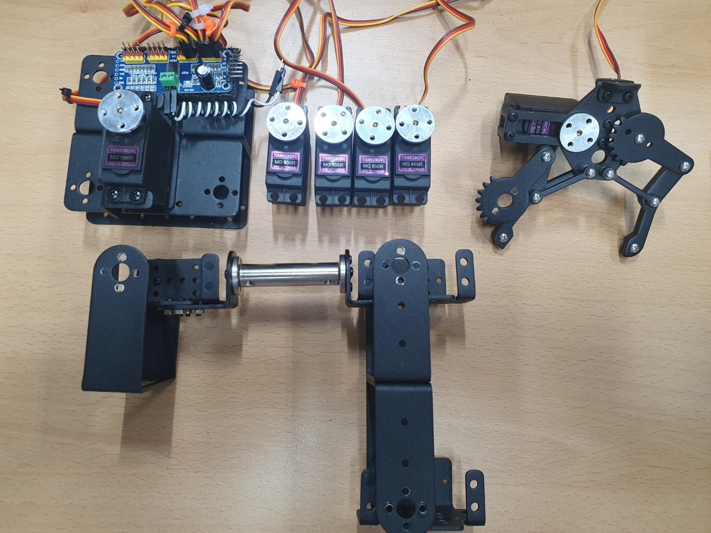
[picture 5] parts
There is no such thing as auto-calibration with feedback control.
Since I plan to add features incrementally, I will assemble it by resetting the motors to their default positions for now.
[picture 6] motor cali
Download the package source code.
This code is the final version, and we will build it up from scratch in this post series.
$ git clone --recurse-submodules https://github.com/how2flow/ros2_axis6
Simply downloading the source code won’t make the programs run immediately.
As mentioned above, configure the ROS2 package execution environment referring to the README.
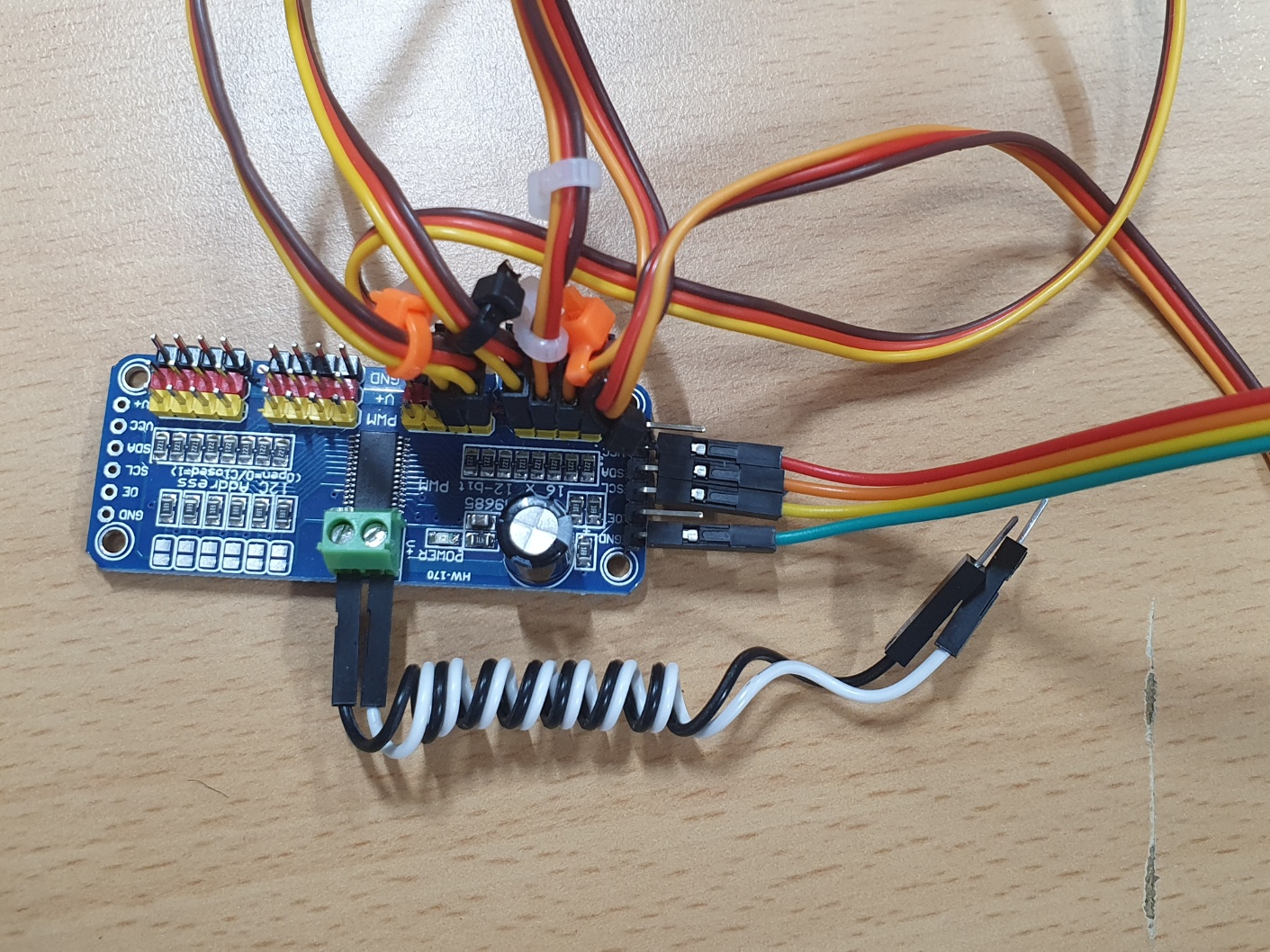
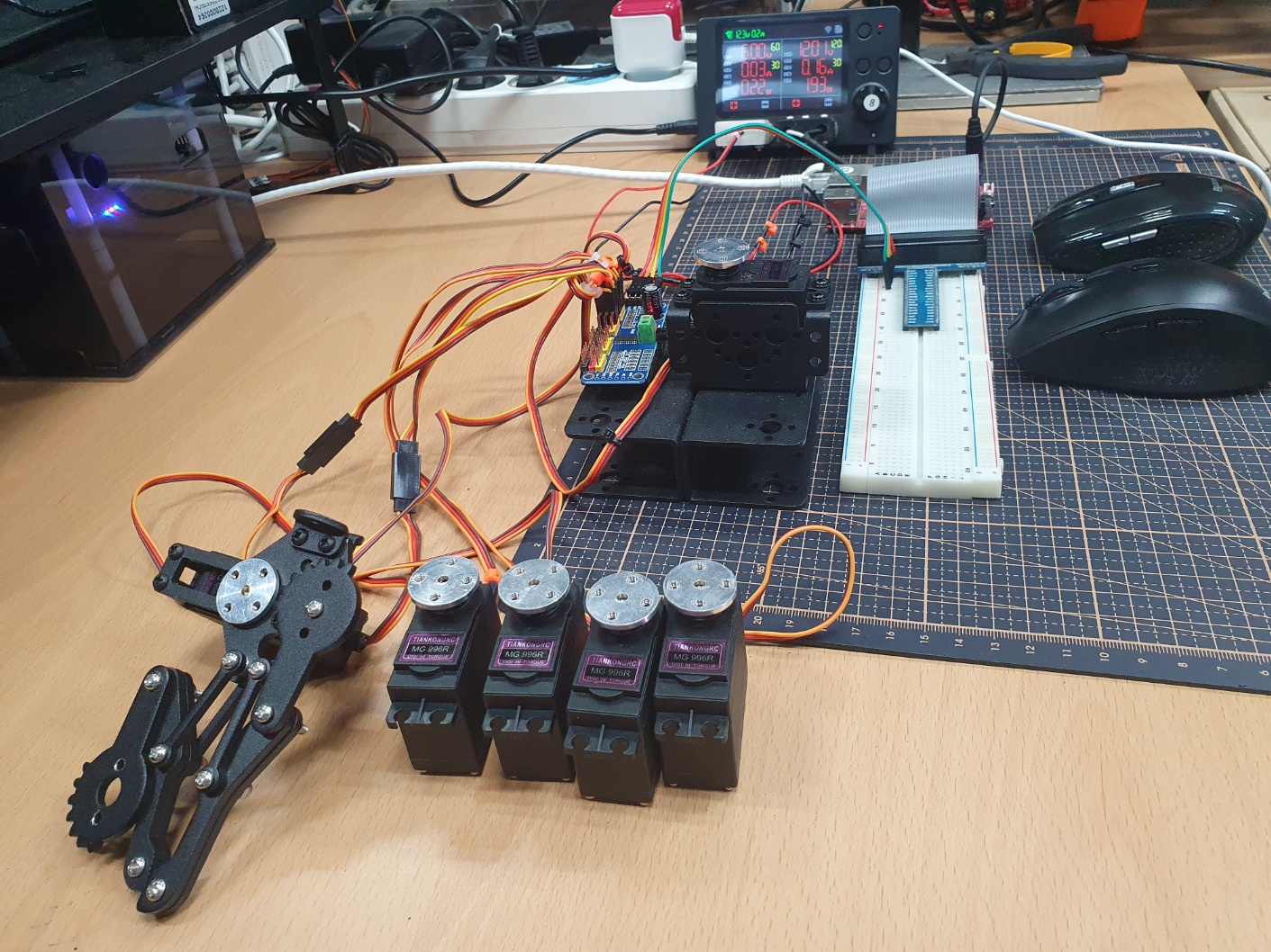
This is the complete circuit diagram.
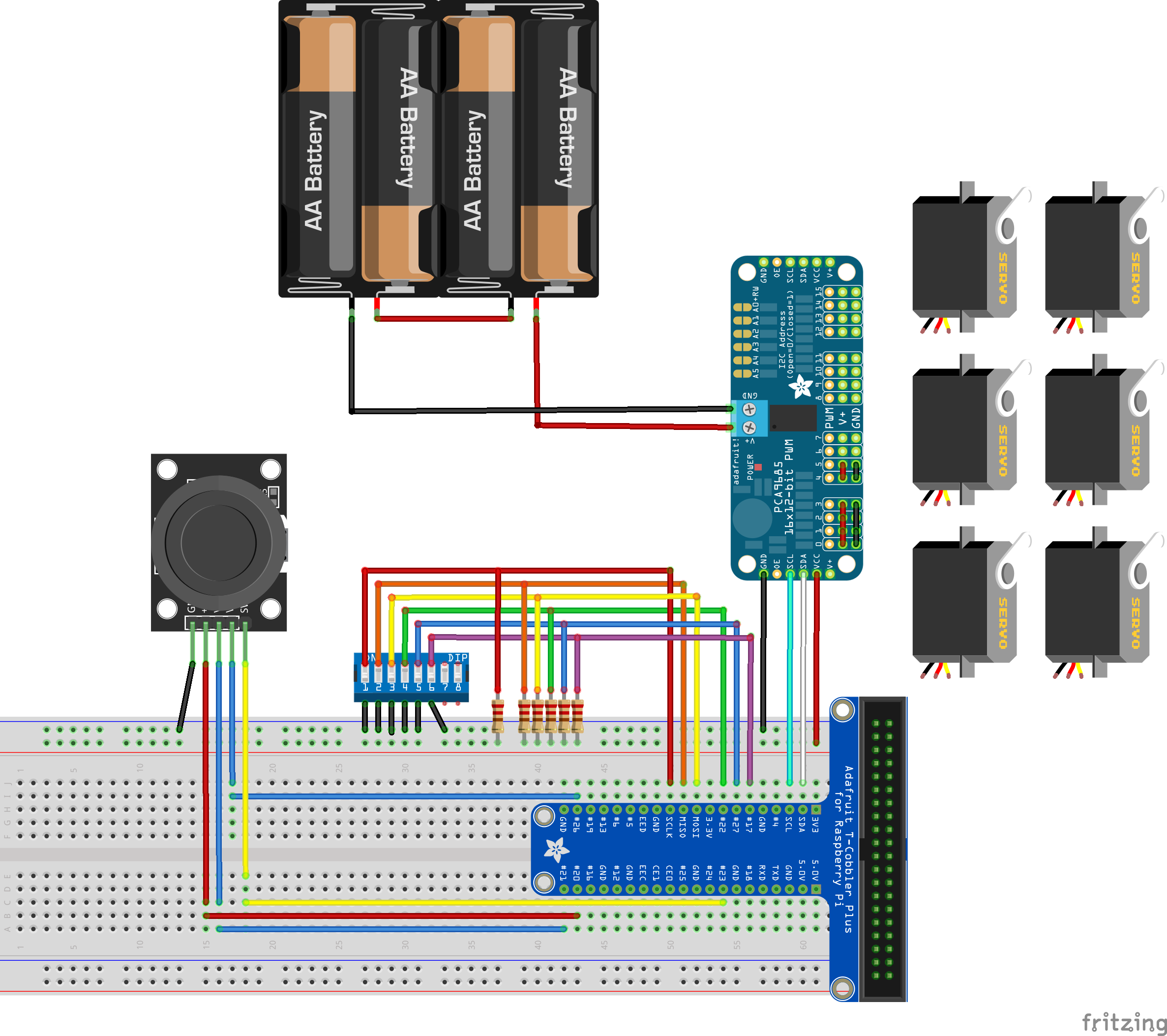
[picture 7] circuit
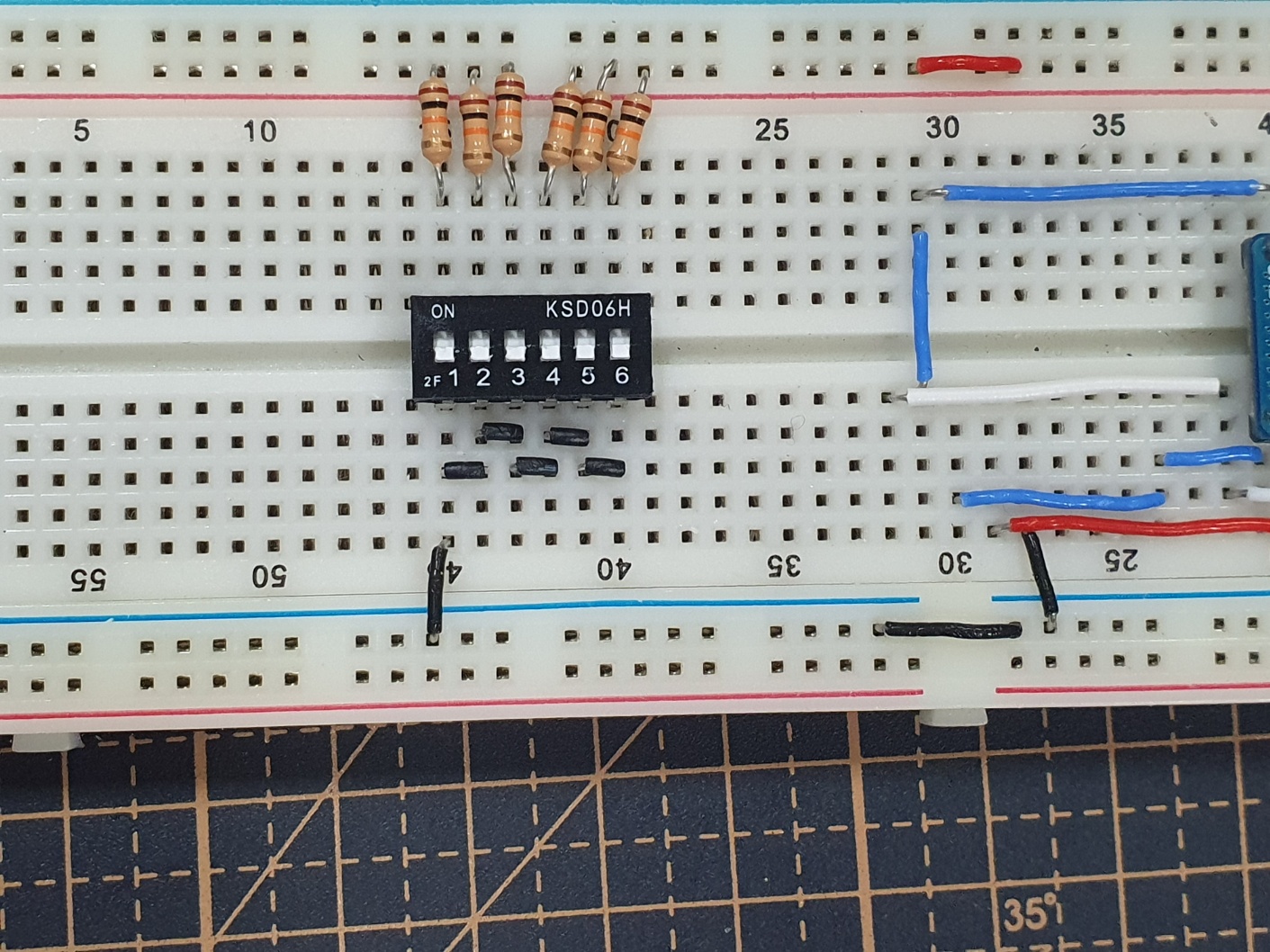
When configuring the circuit, tie the DIP-SWITCH section to GND.
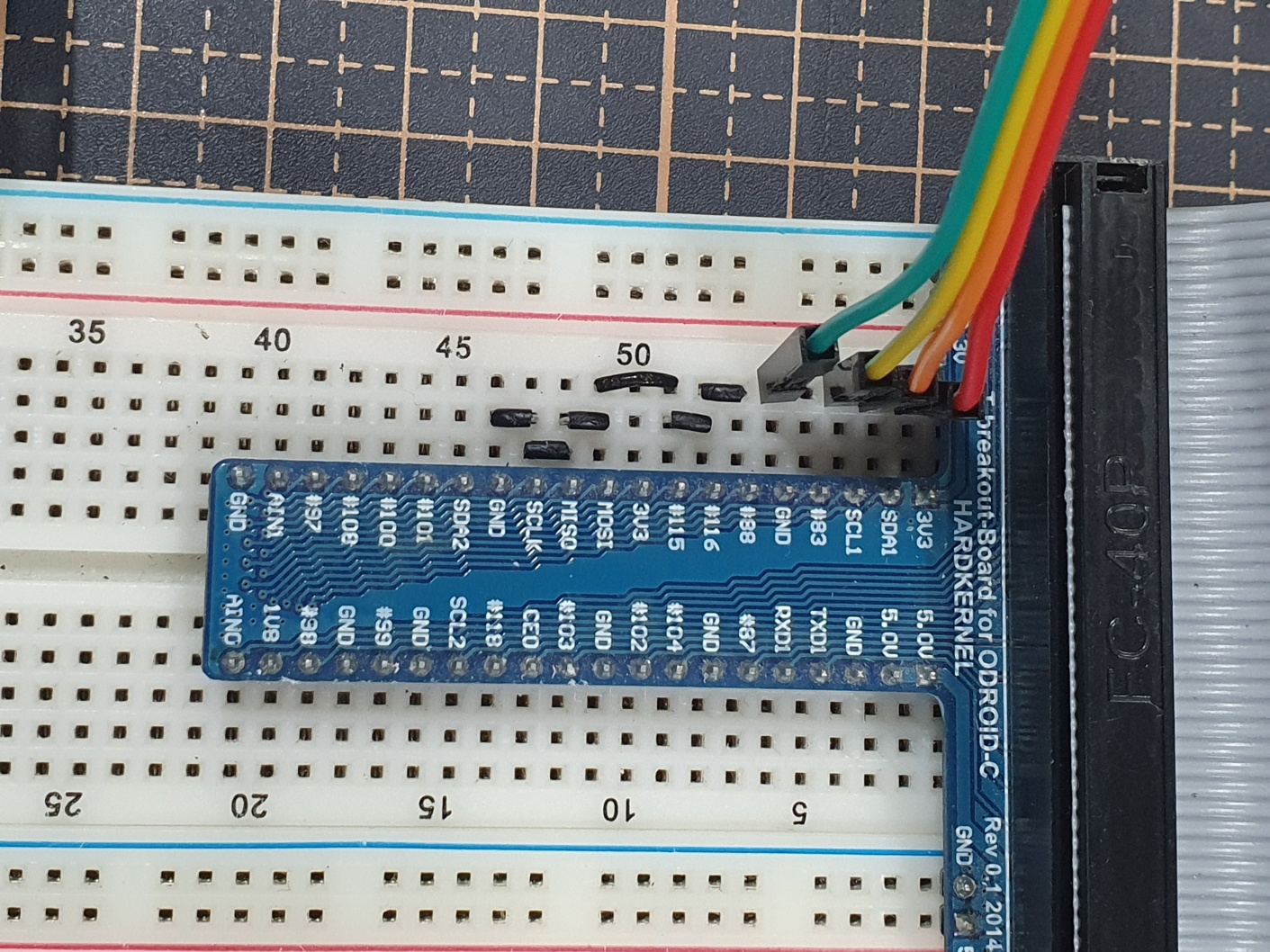
[picture 8] circuit for test
You can leave the breadboard as shown in the photo.
Connect an external power supply (at least 6V/3A) to the pca9685.
Build the downloaded ROS2 package and run the program.
$ cd ~/robot_ws
$ ln -s ~/ros2_axis6 .
$ ln -s ~/ros2_axis6/how2flow_interfaces .
$ cb
$ source ~/.bashrc
$ ros2 run axis6 operator
Connect and secure the motor horns (except for the gripper) as shown in the following photo.
[picture 9] calibrated motors
This photo shows the secured motor horns.
[picture 10] calibrated motors 2
The motors are not connected to external power in the photo, but they must be connected during assembly.
Secure the gripper like this.
[picture 11] calibrated motors 3
Use shorter bolts when connecting the gripper to the arm.
These are included with the product.
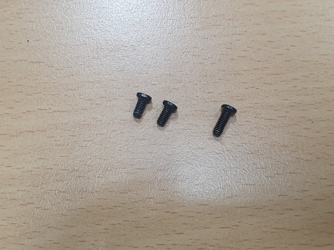
[picture 12] endeffector bolt
Assemble the gripper.
Assemble in the order shown in the photos.
[picture 13] link endeffector 1
[picture 14] link endeffector 2
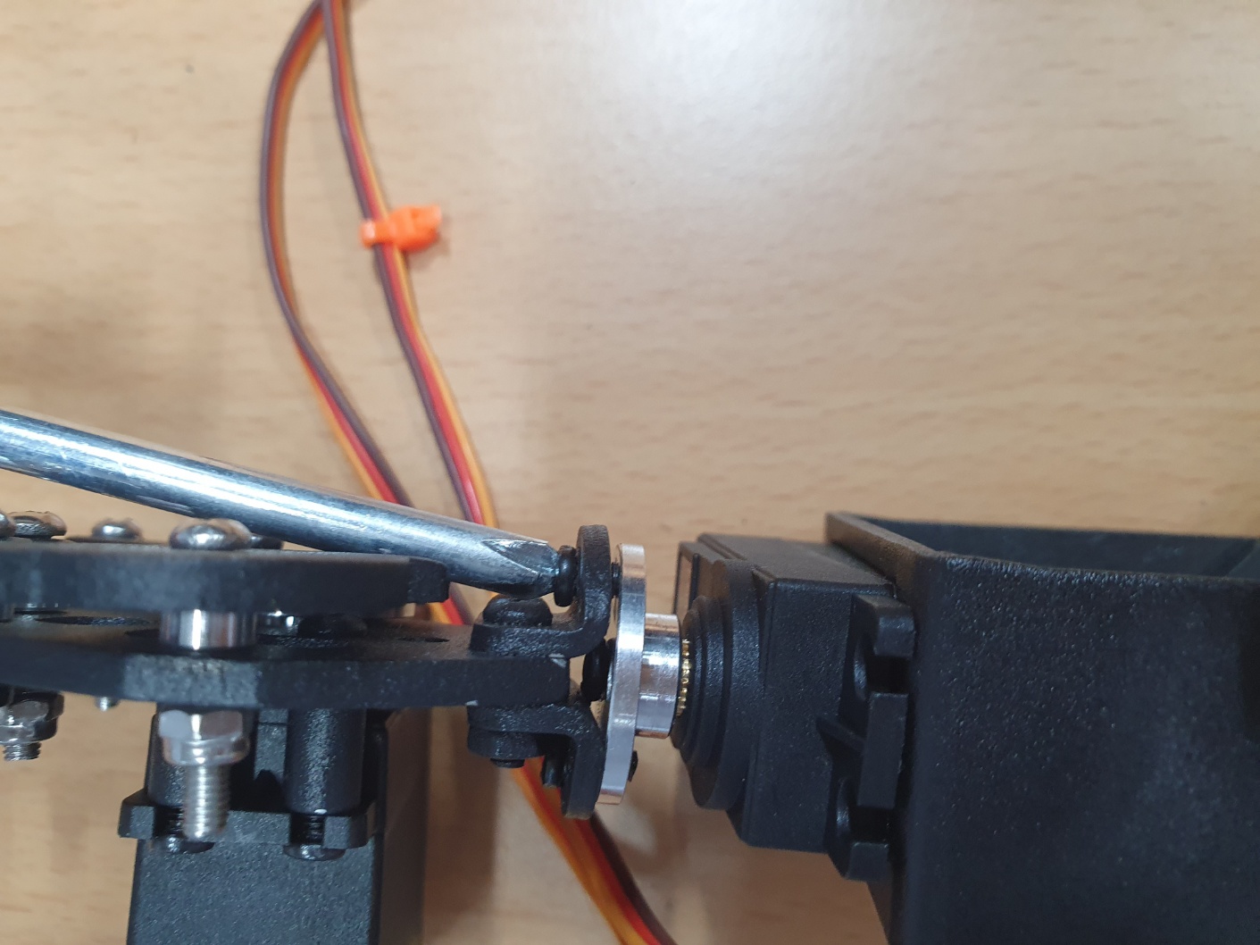
Secure the motor to the arm frame.
Again, assemble in the order shown in the photos.
[picture 15] link motor 1
[picture 16] link motor 2
[picture 17] link motor 3
This is how the assembly should look.
[picture 18] assembly arm
Now, connect the base pillar and the arm.
[picture 19] link arm and base
After connecting the remaining motors, it should look like this.
[picture 20] assembly 2
It’s a good idea to organize the wires if possible.
[picture 21] clean up the wires
Refer to the complete circuit diagram again and configure the circuit.
I configured the circuit on a breadboard.
[picture 22] circuit
[picture 23] breadboard circuit 1
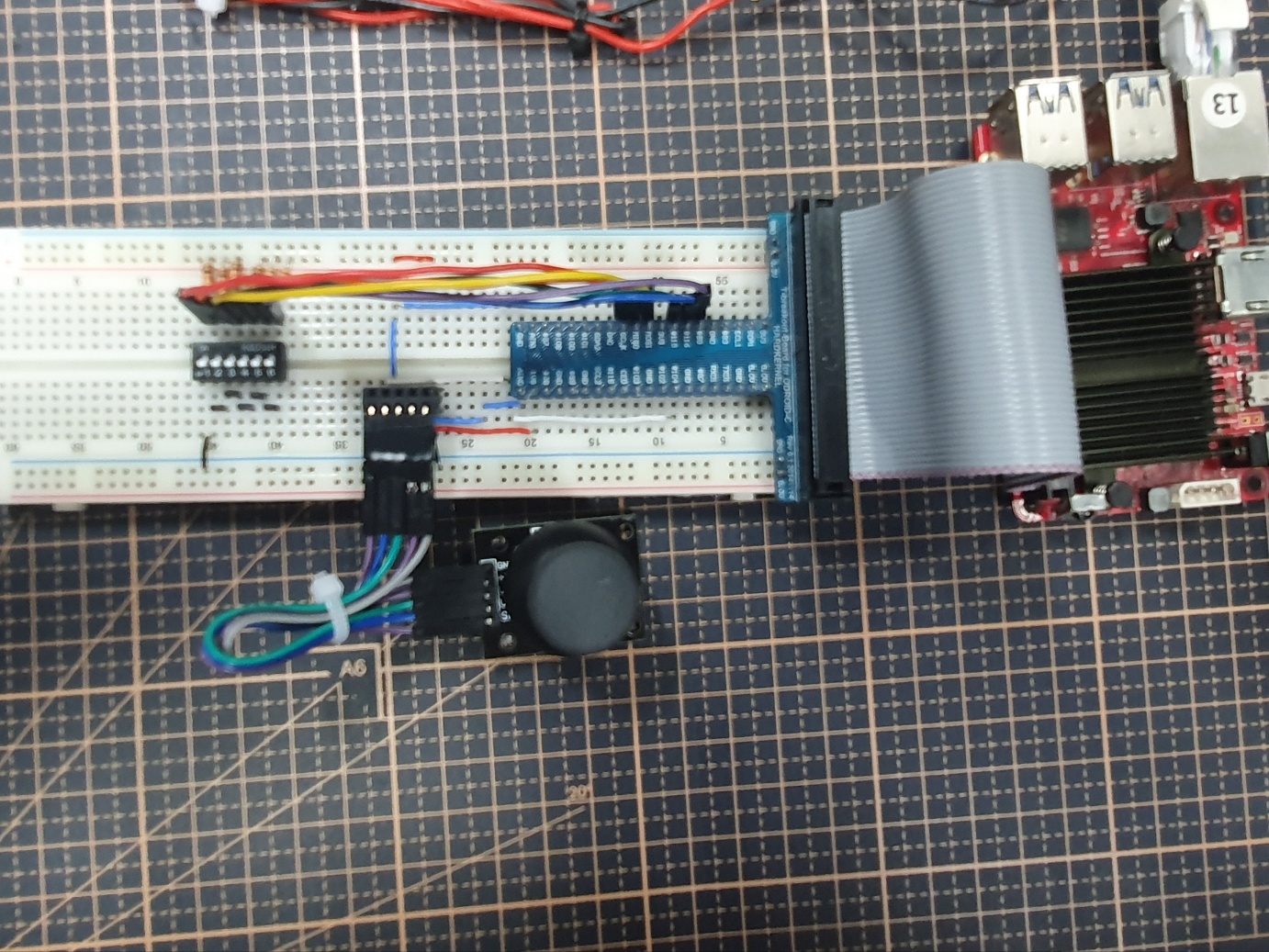
[picture 24] breadboard circuit 2
Now, run the package again to confirm that the robot arm moves to its initial position.
$ ros2 run axis6 operator

Leave a comment