
GIC Software Architectural Design (SWE.2)
Note: The images in this document were generated using AI.
1 Module Overview
1.1 Purpose of Module
The GIC Software Architectural Design defines the high-level structure and components of the GICv3 and ITS driver. It serves as a bridge between the software requirements (SWE.1) and the detailed design (SWE.3), ensuring that the system is modular, maintainable, and meets all functional and non-functional requirements.
1.2 Role of Module
The GIC module acts as the central interrupt controller driver within the Linux Kernel. Its primary roles are:
- Abstraction: Providing a unified
irq_chipinterface to the kernel, hiding hardware complexities. - Routing: Dynamically routing interrupts (SPIs, LPIs) to appropriate CPU cores based on affinity settings.
- Translation: Managing the ITS to translate device MSIs into LPIs.
- Power Management: Handling context save/restore during system power transitions.
1.3 Boundary of Module
- Interfaces: The module interacts with the Kernel IRQ Subsystem (generic layer), ACPI/Device Tree (firmware), and the physical GIC hardware (memory-mapped registers).
- Scope: Includes
irq-gic-v3.c,irq-gic-v3-its.c, and related header files. - Exclusions: Does not include the generic IRQ domain logic or the PCI subsystem itself.
2 Module Architecture
2.1 Implementation View
The implementation view shows the static code structure and file organization.
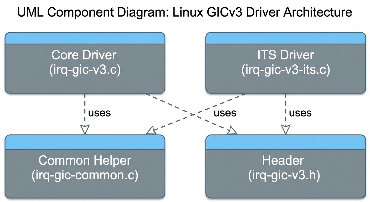
Role of Implementation elements
| Implementation Element | Role |
|---|---|
GICv3 Core (irq-gic-v3.c) |
Handles initialization of Distributor and Redistributors, and basic IRQ chip operations (mask/unmask/eoi). |
ITS Driver (irq-gic-v3-its.c) |
Manages ITS hardware, allocates LPIs, and handles MSI domain operations. |
GICv3 Header (irq-gic-v3.h) |
Defines register offsets and hardware-specific constants. |
GIC Common (irq-gic-common.c) |
Shared helper functions for GICv2 and GICv3. |
2.2 Runtime View
The runtime view illustrates the dynamic behavior and interaction of objects during execution.
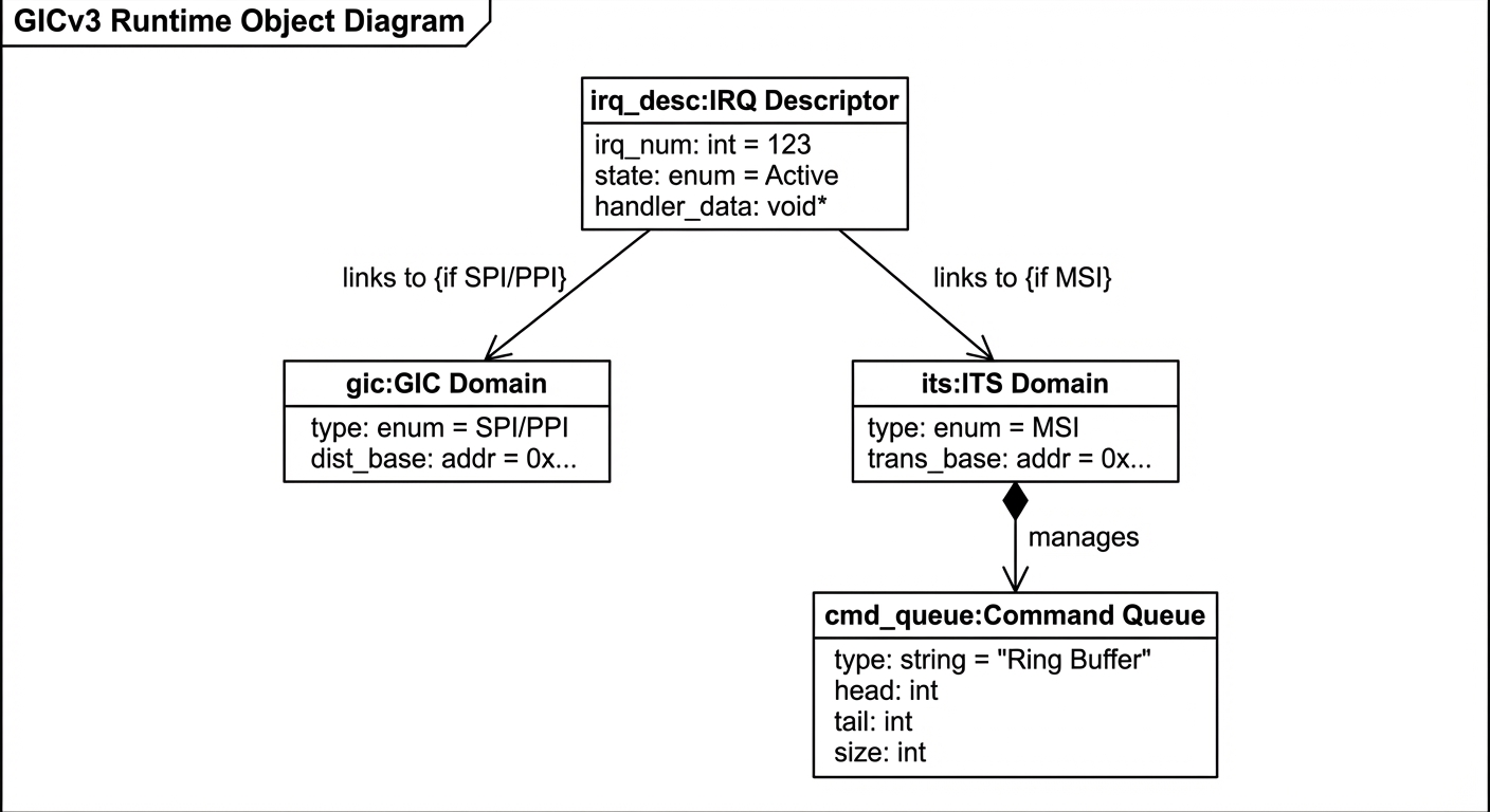
Role of runtime elements
| Runtime Element | Role |
|---|---|
| GIC Domain | Represents the IRQ domain for SPIs and PPIs. |
| ITS Domain | Represents the MSI domain for PCI/Platform devices. |
| IRQ Descriptor | Kernel object representing a single interrupt line, linked to GIC chip data. |
| Command Queue | In-memory circular buffer used to send commands to the ITS. |
Role of connector
| Connector | Role |
|---|---|
| Function Calls | Direct invocation of internal functions. |
| IRQ Domain Ops | Virtual function table (irq_domain_ops) used by the kernel core to call into the driver. |
| MMIO | Memory-Mapped I/O read/write operations to control hardware. |
Runtime-to-Implementation Mapping
| Runtime View Elements | Implementation View Elements |
|---|---|
| GIC Domain | struct irq_domain in irq-gic-v3.c |
| ITS Domain | struct irq_domain (MSI) in irq-gic-v3-its.c |
| Command Queue | cmd_write functions in irq-gic-v3-its.c |
2.3 Allocation View
The allocation view maps software components to hardware units.
- Distributor Driver: Runs on the Boot CPU (initially) and manages the single GICD hardware block.
- Redistributor Driver: Instantiated per CPU core, managing the local GICR block.
- ITS Driver: Manages one or more ITS hardware blocks, allocating system memory (RAM) for Device and Collection tables.
3 Module Interaction
3.1 Interaction: MSI Allocation & Interrupt Delivery
This interaction describes how a PCI device requests an interrupt and how it’s delivered.
MSI Allocation Sequence
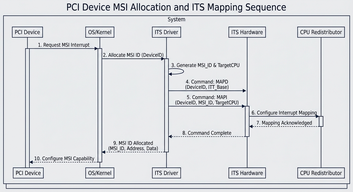
Flow:
- PCI Device Driver requests MSI.
- Kernel IRQ Subsystem calls
its_irq_domain_alloc. - ITS Driver allocates a Device ID and Event ID.
- ITS Driver sends
MAPDandMAPTIcommands to ITS hardware. - Hardware updates internal Translation Tables (RAM).
4 Annex
4.1 Annex A. Alternative Architecture
4.1.1 Polling Mode
Instead of interrupt-driven handling, the driver could poll the GICD status registers.
- Pros: Deterministic latency (in some cases), no context switch overhead.
- Cons: High CPU usage, wasted power, slow reaction to sporadic events.
- Evaluation: Rejected. Interrupt-driven mode is essential for power efficiency and responsiveness in general-purpose OS.
4.2 Annex B. Alternative Architecture Evaluation
| ID | Quality Attribute | Score | Reason for Evaluation | | :— | :— | :— | :— | | Alt-01 | Power Efficiency | Low | Polling prevents CPU low-power states. | | Alt-02 | Responsiveness | Medium | Depends on polling interval; usually worse than hardware IRQ. | | Evaluation Result | Reject | Polling is unsuitable for primary interrupt controller. |
4.3 Annex C. Selected Architectural Design
The selected design is the Event-Driven / Interrupt-Driven Architecture integrated with the Linux Kernel irq_chip framework.
- Justification: Aligns with standard Linux patterns, supports hardware virtualization (KVM), maximizes power efficiency, and leverages GICv3 hardware acceleration (ITS).
5 Terms and Abbreviations
| Terms and Abbreviations | Description |
|---|---|
| GICD | GIC Distributor |
| GICR | GIC Redistributor |
| LPI | Locality-specific Peripheral Interrupt |
| ITS | Interrupt Translation Service |
| MADT | Multiple APIC Description Table (ACPI) |
6 References
| Documents Name | Version |
|---|---|
| GIC Software Requirements Specification (SWE.1) | 1.0 |
| Linux Kernel Documentation (irq-domain) | 6.12 |
Leave a comment